

Vehicle brake system
a brake system and brake technology, applied in the direction of brake systems, braking components, transportation and packaging, etc., can solve the problem and achieve the effect of increasing the production cost of the brake system
- Summary
- Abstract
- Description
- Claims
- Application Information
AI Technical Summary
Benefits of technology
Problems solved by technology
Method used
Image

Examples
first embodiment
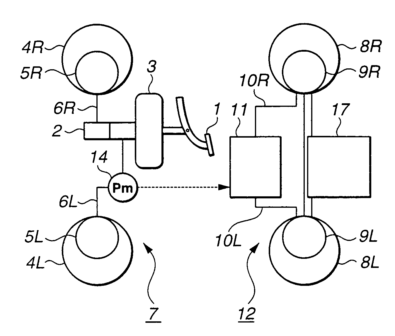
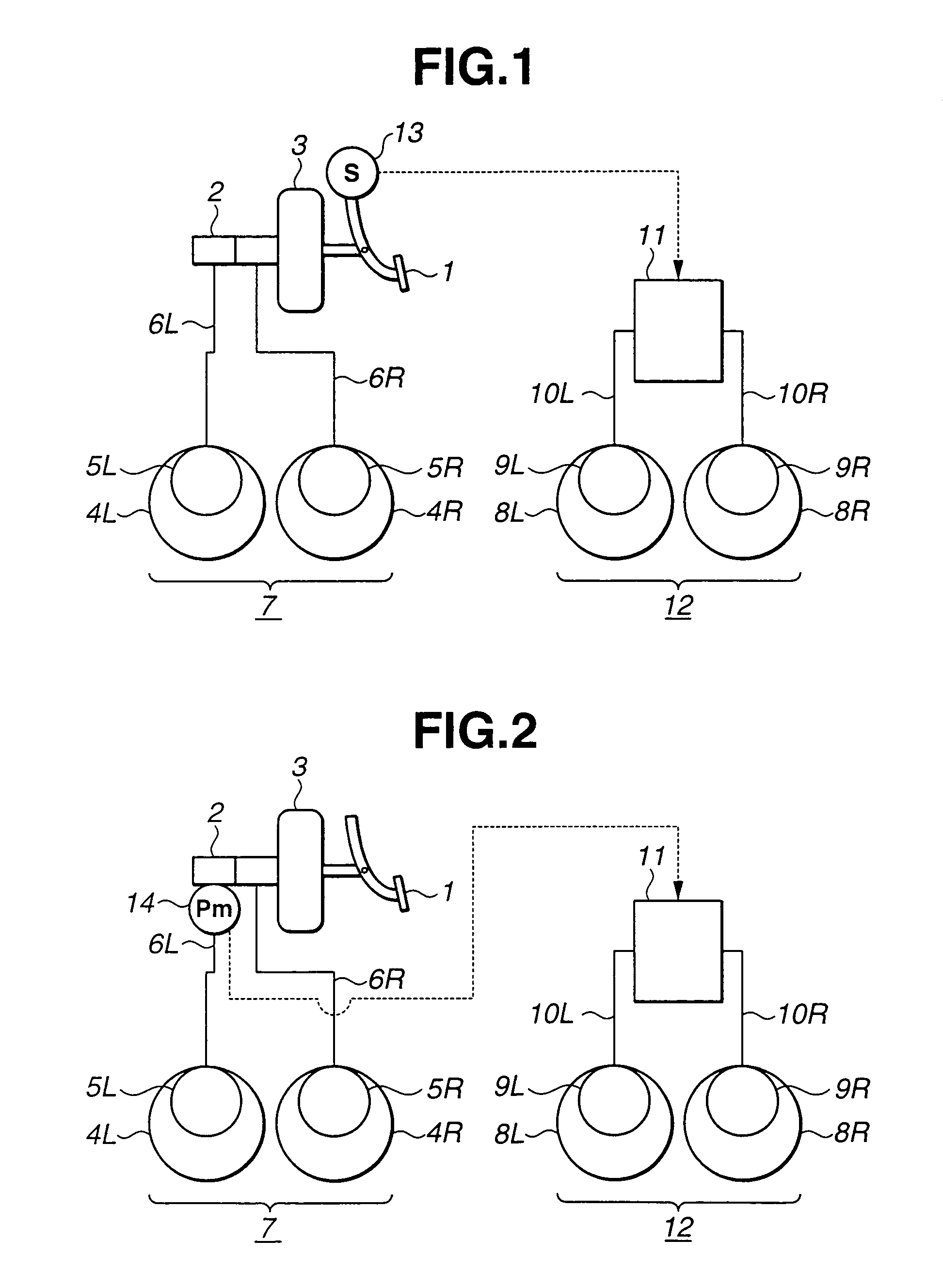
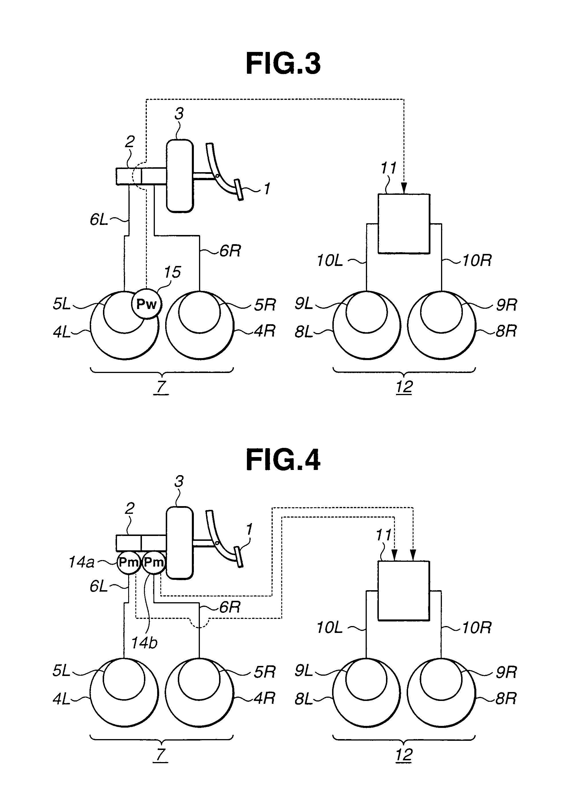
[0034]Referring to FIG. 1, there is shown a brake system for a vehicle in accordance with the present invention. The brake system comprises a brake pedal 1 which is depressed by a driver to generate a brake manipulation force and a master cylinder 2 which receives the brake manipulation force from brake pedal 1. A booster 3 is disposed between brake peal 1 and master cylinder 2 and may be of a negative pressure type, positive pressure type or hydraulic pressure type. Booster 3 boosts the brake manipulation force of brake pedal 1 and supplies the boosted brake manipulation force to master cylinder 2.
[0035]Master cylinder 2 is a tandem master cylinder having two hydraulic pressure outlets. Brake conduits 6L and 6R extend from the two hydraulic pressure outlets to brake units 5L and 5R of right and left front wheels 4L and 4R, respectively. Each of brake units 5L and 5R includes a brake drum or disc brake. These two independent circuits construct a first brake system 7. Brake units 9L ...
fourth embodiment
[0097]Referring to FIG. 18, there is discussed the brake system according to the present invention.
[0098]As shown in FIG. 18, a brake pedal 101 applies a brake manipulation force generated by the depressing operation of the driver to a master cylinder 102. The brake manipulation force of brake pedal 101 is inputted to master cylinder 2 through a booster which may be of a negative pressure type, positive pressure type or hydraulic pressure type.
[0099]Master cylinder 102 in this embodiment is a tandem master cylinder and outputs master cylinder hydraulic pressure Pm corresponding to the brake manipulation force using working fluid of reservoir 102a from two hydraulic pressure outlets 102L and 102R when an inner piston cup of master cylinder 102 is depressed by the brake manipulation force.
[0100]Two brake conduits 105L and 105R extend from two hydraulic pressure outlets 102L and 102R to brake units (including brake drums or disc brake units) 104FL and 104FR of left and right front whee...
fifth embodiment
[0128]Referring to FIG. 19, there is discussed the brake system according to the present invention. This embodiment is generally the same as the previous embodiment shown in FIG. 18, except that a fail-safe valve 131 is provided in a passage connecting rear wheel brake conduits 113L and 113R of second brake system 114. More specifically, in FIG. 19, the provided position is a part of the conduit between right rear wheel brake conduit 113R connected to left rear wheel brake conduit 113L and second pressure increasing valve 115RR. Herein, fail-safe valve 131 is a normally-open solenoid valve and is energized to be put in closed state when the brake system is put in a fail safe mode under which pressure source 109 becomes inoperable due to electric trouble and it becomes impossible to generate pump pressure Ppr.
[0129]Hereinafter, there is discussed the function of the brake system which comprises the above discussed fail-safe valve 131.
[0130]During a normal state wherein pressure sourc...
PUM
 Abstract
Description
Claims
Application Information