Methods of testing/stressing a charge trapping device

a charge trapping and stressing technology, applied in the direction of individual semiconductor device testing, semiconductor/solid-state device testing/measurement, instruments, etc., can solve the problems of undesirable electron conduction between the source and drain, the type of trap is not particularly useful for effecting an ndr characteristic, and the capability of conventional ndr devices, so as to improve the switching time of the semiconductor transistor device

Inactive Publication Date: 2006-06-13
SYNOPSYS INC
View PDF115 Cites 4 Cited by
  • Summary
  • Abstract
  • Description
  • Claims
  • Application Information

AI Technical Summary

Benefits of technology

[0159]An advantage of the present invention is that the onset of NDR behavior can be controlled through selecting a target trap energy level. In turn, the trap energy level can be engineered through suitable process control parameters such as through selection of a particular impurity species and / or trapping layer dielectric.
[0160]A mask can be used to selectively form the charge trapping region in those areas 1015 where an NDR element is to be formed, and in some instances so that it does not extend across an entire region 1015 of substrate 1000, but is instead limited to some smaller area corresponding to a later gate region of an NDR FET, or even a limited portion of such gate region. In some cases, for example, it may be desirable to form a trapping region only near a source region, or only near a drain region, depending on the expected device biasing and operational characteristics. To maximize “source side” trapping, for example, charge traps can be selectively arranged to extend from a source region, and not extend entirely through the channel to a drain side. A variable distribution of traps might be employed along a length of the channel so as to effectuate a trapping rate that varies correspondingly and results in a faster switching speed.
[0161]It is expected that routine experimentation will yield a variety of trap distributions for optimizing different characteristics of an NDR FET, such as switching speed, VNDR, noise immunity, leakage, subthreshold swing, Vt, etc. Thus it will be understood by those skilled in the art that while it is shown as extending throughout all of region 1015, the invention is not limited to such implementations, and in fact a variety of charge trapping structures may be used advantageously for different applications.
[0162]Thus, the present detailed description continues with a discussion of FIG. 8, which is a schematic cross-sectional view showing the step of forming an initial insulating layer (after sacrificial oxide layer 1018 is removed) on the surface of the substrate in a first region 1015 where an NDR FET of a preferred embodiment is to be formed as part of step 425 described above. This initial insulating layer 1020 functions as part of a gate insulator for a to-be-formed NDR FET, and can also serve as a charge trapping region for such NDR FET. It is formed on the surface of substrate 1000 in active areas 1015 by one of several well-known techniques, including thermal oxidation of silicon. Physical vapor deposition and chemical vapor deposition can also be used. This electrically insulating layer 1020 can consist entirely or in part of SiO2, SiOxNy, Si3N4, or a high-permittivity dielectric material such as metal oxide or metal silicate or their laminates, or, of course, as a combination of one or more different material layers.
[0163]As with other processing steps noted herein, an advantage of the present invention lies in the fact that this layer (as patterned later) can be shared by both conventional and NDR FET devices. Alternatively viewed, from a process integration impact, the existence of such layer in non-NDR regions during these NDR FET formational steps does not negatively impact the structure, performance or reliability of any non-NDR elements. Nonetheless, in some applications it may be desirable to mask and etch layer 1020 in those areas where non-NDR elements are to be formed, so that charge trapping regions ate not formed later across all regions of the substrate.
[0164]In an alternate embodiment, traps are formed by directly implanting the gate insulator layer 1020 using a combination of energies and species that ensure a high concentration at a channel interface and a low concentration in a bulk region of layer 1020.

Problems solved by technology

, which far exceeds the capabilities of conventional NDR devices.
For reasons, which are apparent from the aforementioned King et al. applications, this type of trap, therefore, is not particularly useful for effectuating an NDR characteristic.
The areal concentration of traps should not be excessive, however (i.e., greater than 1014 / cm2), because this can also lead to undesirable electron conduction between the source and drain via trap-to-trap hopping or channel-to-trap-to-channel hopping.
This is done to ensure that the traps do not migrate too far into the trapping region, causing excessive leakage, slow operation, and poor reliability.
In the absence of an anneal step, for example, Boron may undesirably diffuse rapidly with the aid of point defects into a bulk region of the trapping layer, resulting in a high level of gate leakage current.
While a steam anneal can be used (e.g., 10 minutes at 750° C. in steam ambient, followed by 1 minute at 1050° C. in N2) for some embodiments, the beneficial aspects of such approach are not uniform across all implementations.
When the gate is relatively thick, this results in a greater migration / dilution of the trap concentration near the interface, thus resulting in reduced performance.
It should be noted that prior-art NDR devices such as the tunnel diode, resonant tunneling diode, thyristor, real-space transfer transistors, etc. show significantly degraded performance at elevated temperatures.
Apparently, in the experimental wafers, the LDD ion implantation damage was not completely annealed out for the higher dose (3×1015 cm−2) As implant, which resulted in lower peak current and higher valley current and hence degraded PVR.
However, in some cases it also enhances boron diffusion away from the interface (and thereby lowers the trap-state density at the interface) if the gate oxide is thick.
The vast majority of these carriers will not have sufficient kinetic energy to cause new traps to be formed in the “tunnel oxide”.
It is known that conventional hot carriers in the channel (i.e., >3.1 eV) are responsible for degradation in MOSFET performance, because of the damage which they cause to the oxide interface as well as in the bulk of the oxide.
The energetic electrons which tunnel into the traps embedded within the oxide are generally not “hot” enough to cause damage.
This type of stressing can cause the formation of traps in the insulator as well.
In fact, if a PVR is too high, a circuit might actually operate more slowly since it will take longer for an NDR device to go from a “valley” current state to a “peak” current state.
Traditional methods of making NDR devices do not allow for easy or adequate differentiation of NDR characteristics during a common manufacturing process.

Method used


Image

  • Methods of testing/stressing a charge trapping device
  • Methods of testing/stressing a charge trapping device
  • Methods of testing/stressing a charge trapping device

Examples


Embodiment Construction

[0111]A preferred embodiment of the invention is now described with reference to the Figures provided herein. It will be appreciated by those skilled in the art that the present examples are but one of many possible implementations of the present teachings, and therefore the present invention is not limited by such.

[0112]The present invention is expected to find substantial uses in the field of integrated circuit electronics as an additional fundamental “building block” for digital memory, digital logic, and analog circuits. Thus, it can be included within a memory cell, within a Boolean function unit, and similar such environments.

BRIEF SUMMARY OF PRIOR ART

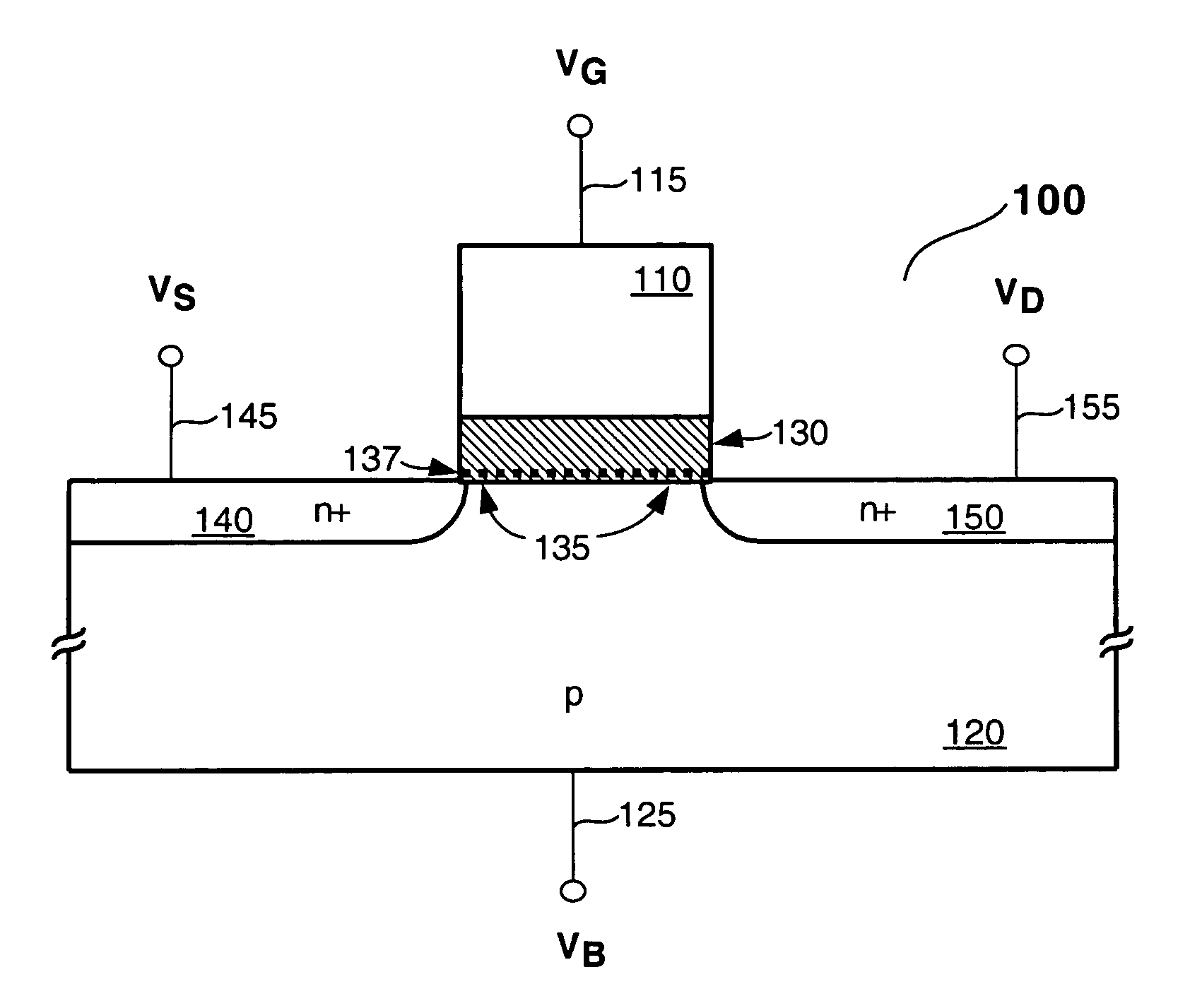
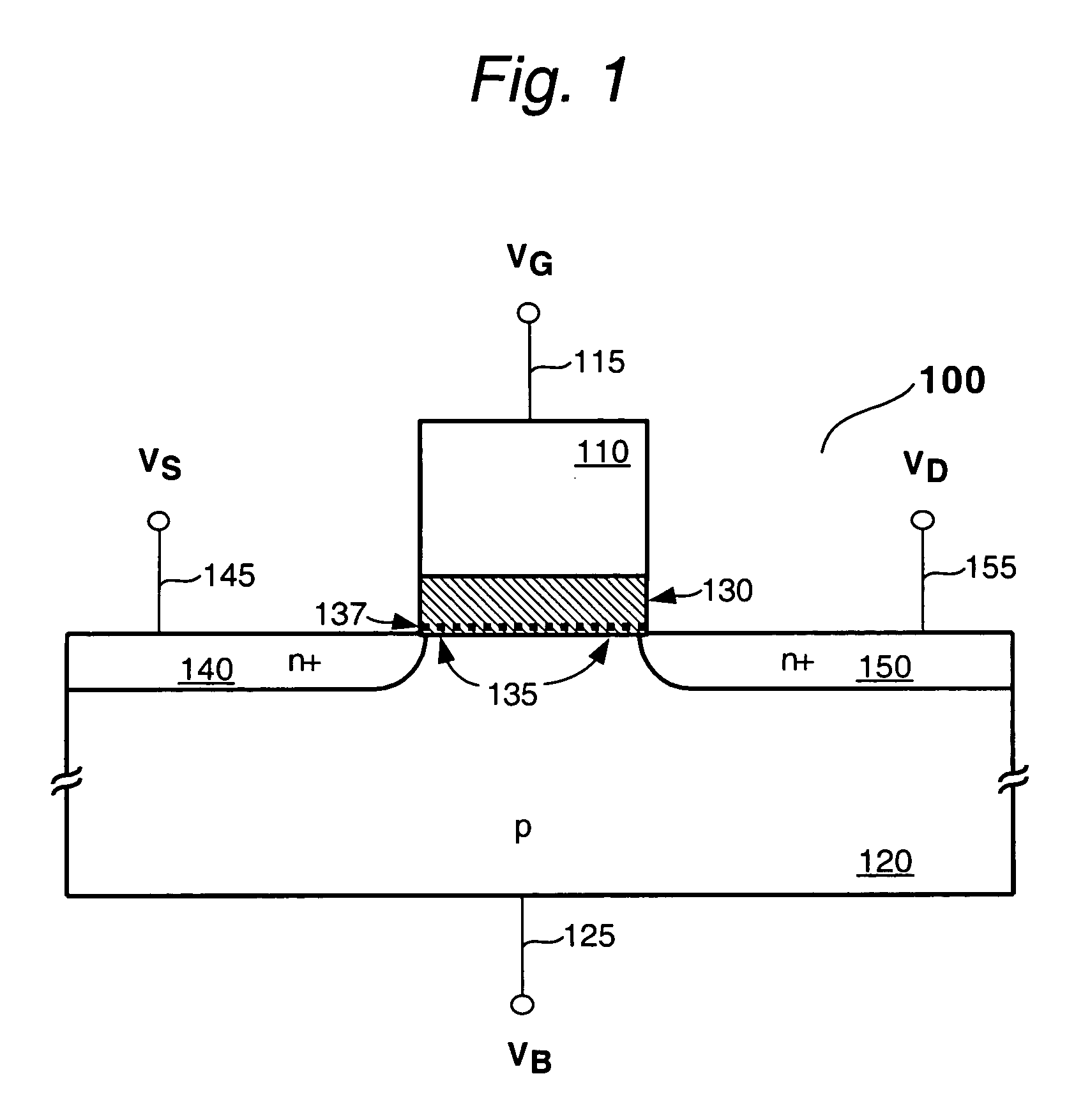
[0113]FIG. 1 shows a prior art NDR FET 100 of the type described in the King et al. applications noted earlier. This device is essentially a silicon based MISFET that includes an NDR characteristic as well. Thus, the features of device 100 are created with conventional MOS based FET processing, modified where appropriate as to in...


PUM


Abstract

A method of testing / stressing a charge trapping device, such as a negative differential resistance (NDR) FET is disclosed. By operating / stressing a charge trap device during / after manufacture, a distribution of charge traps can be altered advantageously to improve performance.

Description

CROSS REFERENCE TO RELATED APPLICATIONS[0001]The present application claims priority to and is a continuation of Ser. No. 10 / 322,080, Methods of testing / stressing a charge trapping device, filed Dec. 17, 2002 now U.S. Pat. No. 6,806,117, which in turn is a continuation-in-part of the following applications which are hereby incorporated by reference as if fully set forth herein:[0002]1. Method of Forming a Negative Differential Resistance Device; Ser. No. 10 / 314,735 filed Dec. 9, 2002 now U.S. Pat. No. 6,980,467;[0003]2. Process for Controlling Performance Characteristics of a Negative Differential Resistance (NDR) Device; Ser. No. 10 / 314,785 filed Dec. 9, 2002 now U.S. Pat. No. 6,970,580;[0004]3. Charge Trapping Device & Method of Forming the Same; Ser. No. 10 / 314,510 filed Dec. 9, 2002 now U.S. Pat. No. 6,849,483.[0005]The aforementioned Ser. No. 10 / 322,080 is related to the following applications which are hereby incorporated by reference as if fully set forth herein:[0006]4. Inte...

Claims


Application Information

Patent Timeline
Patent Type & Authority Patents(United States)
IPC IPC(8): H01L21/00H01L21/265H01L21/28H01L21/336H01L21/8234H01L21/8238H01L21/8246H01L27/088H01L27/105H01L29/423H01L29/51H01L29/78
CPCH01L21/265H01L29/78H01L21/28185H01L21/28194H01L21/28282H01L21/823462H01L21/823857H01L27/088H01L27/105H01L27/11568H01L29/42332H01L29/513H01L29/66833H01L21/2652H01L29/512H01L29/517H01L29/518H01L29/40117H10B43/30H01L21/26513
Inventor KING, TSU-JAE
Owner SYNOPSYS INC
Why Eureka
Try Eureka