System for providing assured power to a critical load

Inactive Publication Date: 2006-06-13
INT FUEL CELLS
View PDF14 Cites 58 Cited by
  • Summary
  • Abstract
  • Description
  • Claims
  • Application Information

AI Technical Summary

Benefits of technology

[0012]According to the invention, there is provided a relatively economical and reliable power system for providing substantially uninterrupted electric power to one or more critical loads. A first power source comprising at least one, and possibly multiple, fuel cell power plants, normally provides sufficient power to supply at least the critical loads. A second power source, such as the utility grid, also provides sufficient power to supply the critical loads. The fuel cell power plant(s) is/are adapted to be, and is/are, normally substantially continuously connected to the critical loads and are normally substantially continuously providing significant power to at least the critical loads. A high-speed isolation switch, or static switch, operates to rapidly and seamlessly connect and disconnect the utility grid to the critical load(s) and to the fuel cell power plant(s), for economical continuous usage of the fuel cell power plant(s). Significant economy is realized by having the substantially continuously operating fuel cell(s) normally substantially continuously connected to the load, and n

Problems solved by technology

However, from time to time discontinuities and/or departure from those standards do occur.
If they are brief or modest, most loads are relatively insensitive to those events.
Even brief interruptions in the standardized supply of electric power by the utility grid may cause the computer or control to malfunction, with sometimes costly, and always bothersome, consequences.
On the other hand, some applications of multi-phase digital electronic equipment, such as motor controls and the like, may not tolerate interruptions greater than about 8.3 ms.
The power available on the utility grids is not presently capable of meeting this requirement on a substantially continuous basis.
This arrangement, though effective, requires a number of costly components that are in use only during the intervals when the utility grid power is unsatisf

Method used


Image

  • System for providing assured power to a critical load
  • System for providing assured power to a critical load
  • System for providing assured power to a critical load

Examples


Example

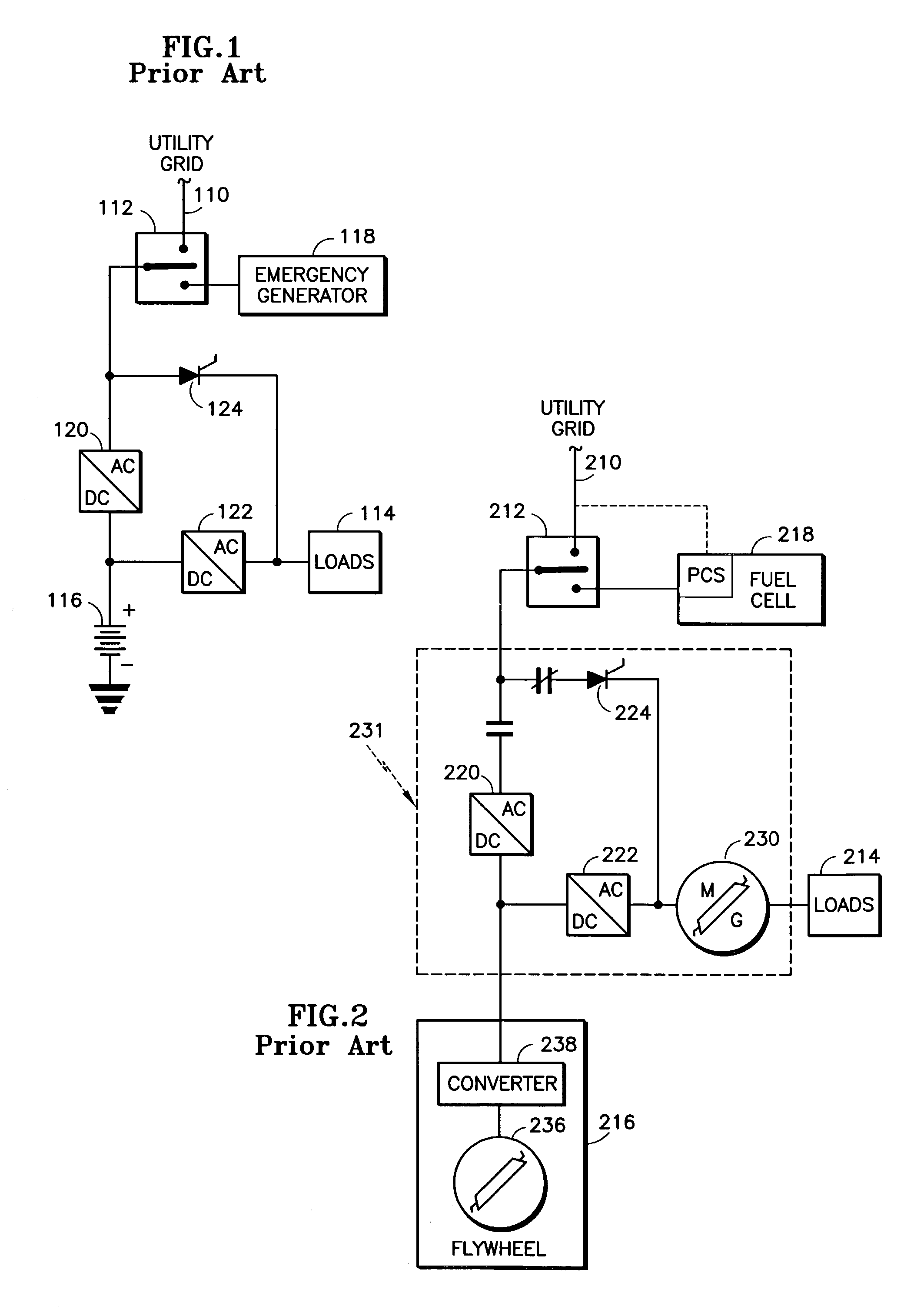
[0020]Referring to the Drawings, FIGS. 1 and 2 depict prior types of uninterrupted power systems as previously described in the Background Art.

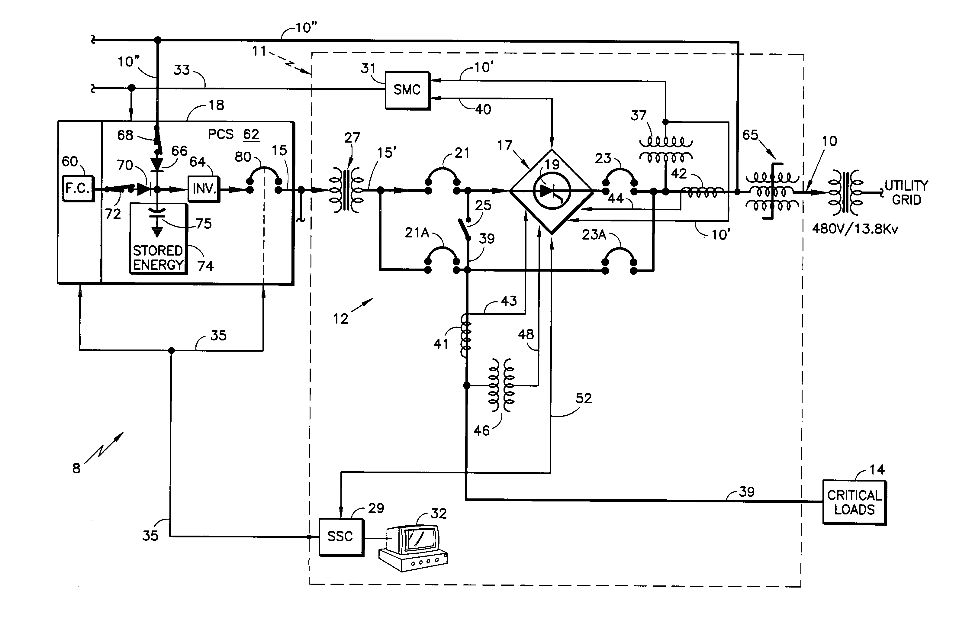
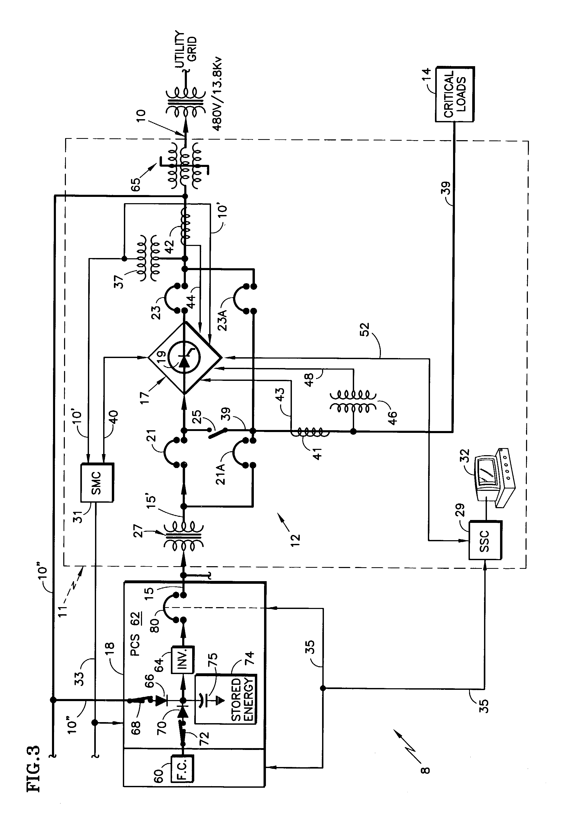
[0021]Referring to FIG. 3, there is depicted a schematic block diagram, partly in detail, of a power system 8 in accordance with the invention. The power system 8 is connected to utility grid bus 10, and employs one or more fuel cell power plant(s) 18 at a site, for supplying 3-phase power substantially continuously to and through load contactors (not shown), to load(s) 14, usually also at the site. For simplicity, a “one line” diagram, or representation, is used herein to depict the 3-phase supply lines, as well as their included switches, etc. The grid 10, the fuel cell power plant(s) 18, and the load(s) 14 are interconnected and controlled through a site management system (SMS), generally represented by the broken line block, or grouping, 11. The load(s) 14 typically include a number of individual customer loads, at least some of which req...


PUM


Abstract

A first AC power source comprising a power plant (18), and a second power source, typically grid (10), are normally connected via a high speed isolation switching means (19) to provide sufficient AC power to a critical load (14). The power plant (18) comprises a power generating means, e.g. a fuel cell, (60) and a power conditioning system (PCS) (62) having an inverter (64). Power assurance means (65; 10″, 66, 64, 70; 74, 75) is/are operatively connected to at least one of the first and second power sources to enhance an even and continuous supply of power to the critical load (14). The power assurance means (65; 10″, 66, 64, 70; 74, 75) is/are operatively connected to the PCS inverter (64), and may be one, or a combination of, a surge suppression means (65), a double-conversion power connection means (10″, 66, 64, 70) having a rectifier (66); and/or stored energy means (74), such as a capacitor (75).

Description

[0001]This application is a continuation-in-part of U.S. patent application Ser. No. 09 / 782,402 filed Feb. 13, 2001 now U.S. Pat. No. 6,465,910.TECHNICAL FIELD[0002]This invention relates generally to power systems, and more particularly to power systems for providing an assured, or uninterruptible, supply of electrical power to one or more critical loads. More particularly still, the invention relates to such power systems employing fuel cells as a source of electrical power.BACKGROUND ART[0003]By far, the most common source of electrical power for a great variety of loads is via the extensive power grid provided by the various electric utilities. The electrical power available on the utility grid is generally fairly reliable as to continuity and adherence to established standards of voltage, frequency, phase, etc. However, from time to time discontinuities and / or departure from those standards do occur. If they are brief or modest, most loads are relatively insensitive to those ev...

Claims


Application Information

Patent Timeline
IPC IPC(8): H02J3/38H01M8/00H02J3/32H02J9/06
CPCH02J3/32H02J9/062Y02B90/14H02J2001/004H02J2300/30Y02B90/10H02J9/00H02J7/00
Inventor YOUNG, DOUGLAS GIBBONSHEALY, HERBERT C.
Owner INT FUEL CELLS
Why Eureka
Try Eureka