
Method and system for identifying and monitoring repeater traffic in a code division multiple access system

a multiple access system and repeater technology, applied in the field of methods and systems for transceiving information, can solve problems such as difficulty, compromise of usual means of determining the location of users, and difficulty, and achieve the effect of increasing (or decreasing) the repeater coverage area and preventing undesirable operational characteristics

Active Publication Date: 2006-06-13
QUALCOMM INC
View PDF6 Cites 52 Cited by
  • Summary
  • Abstract
  • Description
  • Claims
  • Application Information

AI Technical Summary

Benefits of technology

[0014]An embodiment of the present invention permits the monitoring of a variety of different call and signal characteristics, including the average and standard deviation of the number of calls handled by the repeater per given time interval (which typically varies at different times of day), the length of each call handled by the repeater, the number of dropped calls handled by the repeater. Further, the statistics collected regarding calls handled by the repeater can be compared to similar statistics for calls which are transmitted without the repeater (e.g. comparing dropped calls, call volume, and other factors) to assess repeater performance and whether the sector serviced by the repeater would be better serviced by a base station. The present invention also discloses an embodiment in which the output power of signals emanating from the repeater on the reverse link (from the remote station or cellphone to the base station) remain substantially constant. This permits the power control system to operate without the extra burden of compensating for power fluctuations caused by the discriminant added at the repeater. This also allows the level of “interference” that the repeater provides to other users of the base station to be reduced (e.g. the repeater does not desensitize receivers in the base stations by adding extra receive power above and beyond what a normal repeater might add to the base station receivers. Further, the present invention is usable with a wide variety of mobile telephony waveforms, including CDMA (IS-95 and now CDMA2000), Ev-DO (sometimes HDR), Ev-DV, W-CDMA, and GSM.
[0016](1) The information can be used to change the forward link gain, thus increasing (or decreasing) the repeater coverage area (the area serviced by the repeater).
[0017](2) Generally, if the forward link gain is altered, similar adjustments must be made in the reverse link gain. Reverse link gain can be adjusted to compensate for changes in path loss or gain changes within the repeater (e.g. those due to temperature variation). Information regarding which forward and reverse link transmissions were handled by which repeater can also be used to control the reverse link gain, setting the balance between the forward and reverse links as seen by the remote stations in the repeater coverage area. Repeater gain can also be controlled to prevent undesirable operational characteristics such as transmitter oscillation.

Problems solved by technology

In providing this service, difficulties arise when the cellphone user is communicating with the base station of the cell via a repeater.
In such circumstances, the position determination system cannot distinguish where the cellphone user is, since such systems typically do not identify the signal to the user as having been received from the repeater, and the usual means of determining the user's location (e.g. triangulation using signal strength and other signal measures) can be compromised by passing through the repeater.
For example, a repeater typically adds 4–10 μsec to the signal propagation time, which can cause position ambiguities.
This capability is also difficult to implement unless the base stations are capable of identifying which received transmissions were received via the repeater and which were not (e.g. received directly from the cellphone).

Method used


Image

  • Method and system for identifying and monitoring repeater traffic in a code division multiple access system
  • Method and system for identifying and monitoring repeater traffic in a code division multiple access system
  • Method and system for identifying and monitoring repeater traffic in a code division multiple access system

Examples


Embodiment Construction

[0034]In the following description of an embodiment, reference is made to the accompanying drawings, which form a part hereof, and in which is shown by way of illustration a specific embodiment in which the invention may be practiced. It is to be understood that other embodiments may be utilized and structural changes may be made without departing from the scope of the present invention.

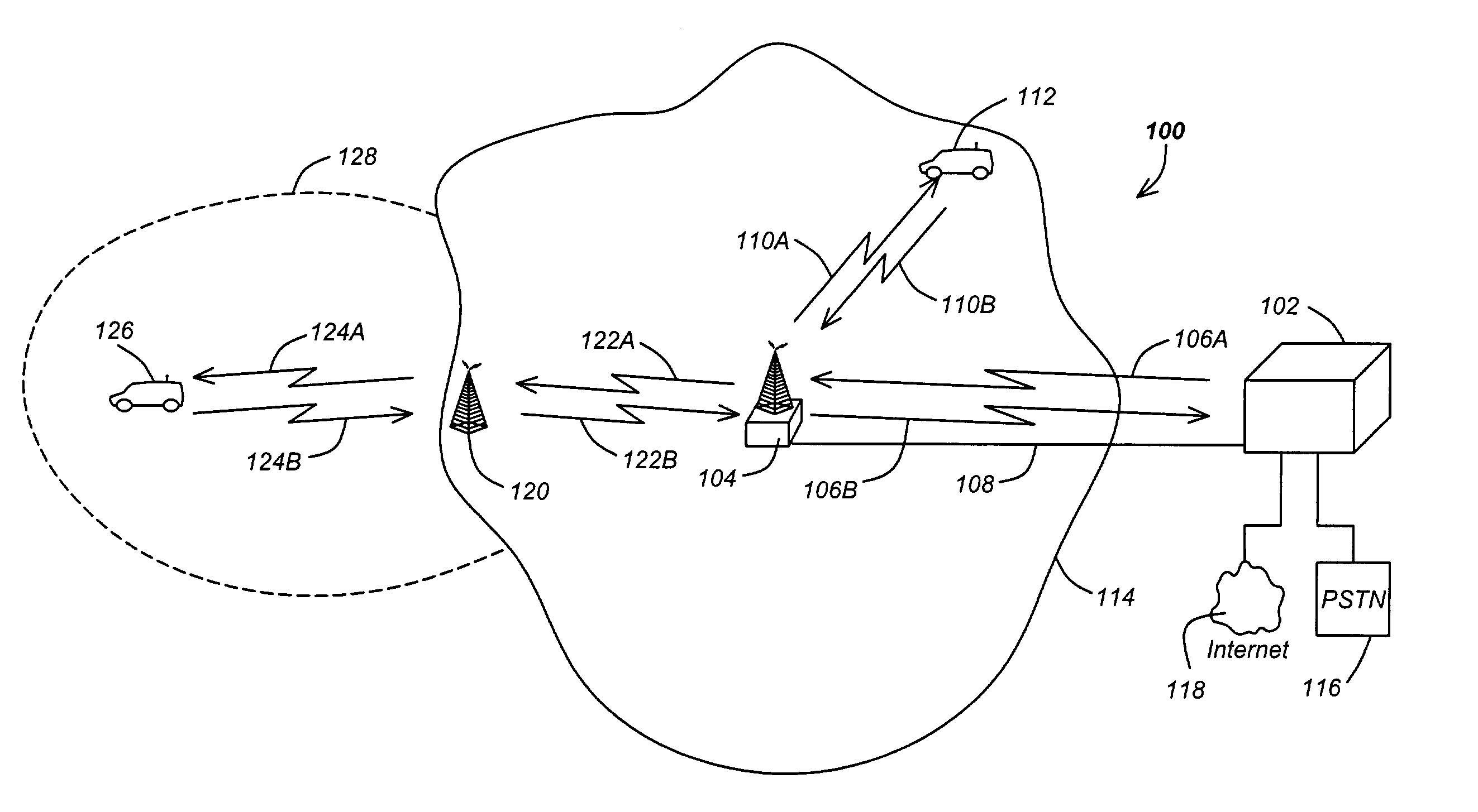
[0035]FIG. 1 is a diagram of a cellular telephone system 100. The cellular telephone system 100 comprises one or more control stations 102, and a plurality of base stations 104. The base stations 104 communicate with remote stations 112 that are within the service area 114 of the base station 104. The remote stations 112 may be mobile stations (e.g. car phones or handheld cellphones) or fixed stations. The service area 114 is generally described as the geographical extent of a locus of points for which a remote station 112 can communicate effectively with the base station. Although the shape of the s...


PUM


Abstract

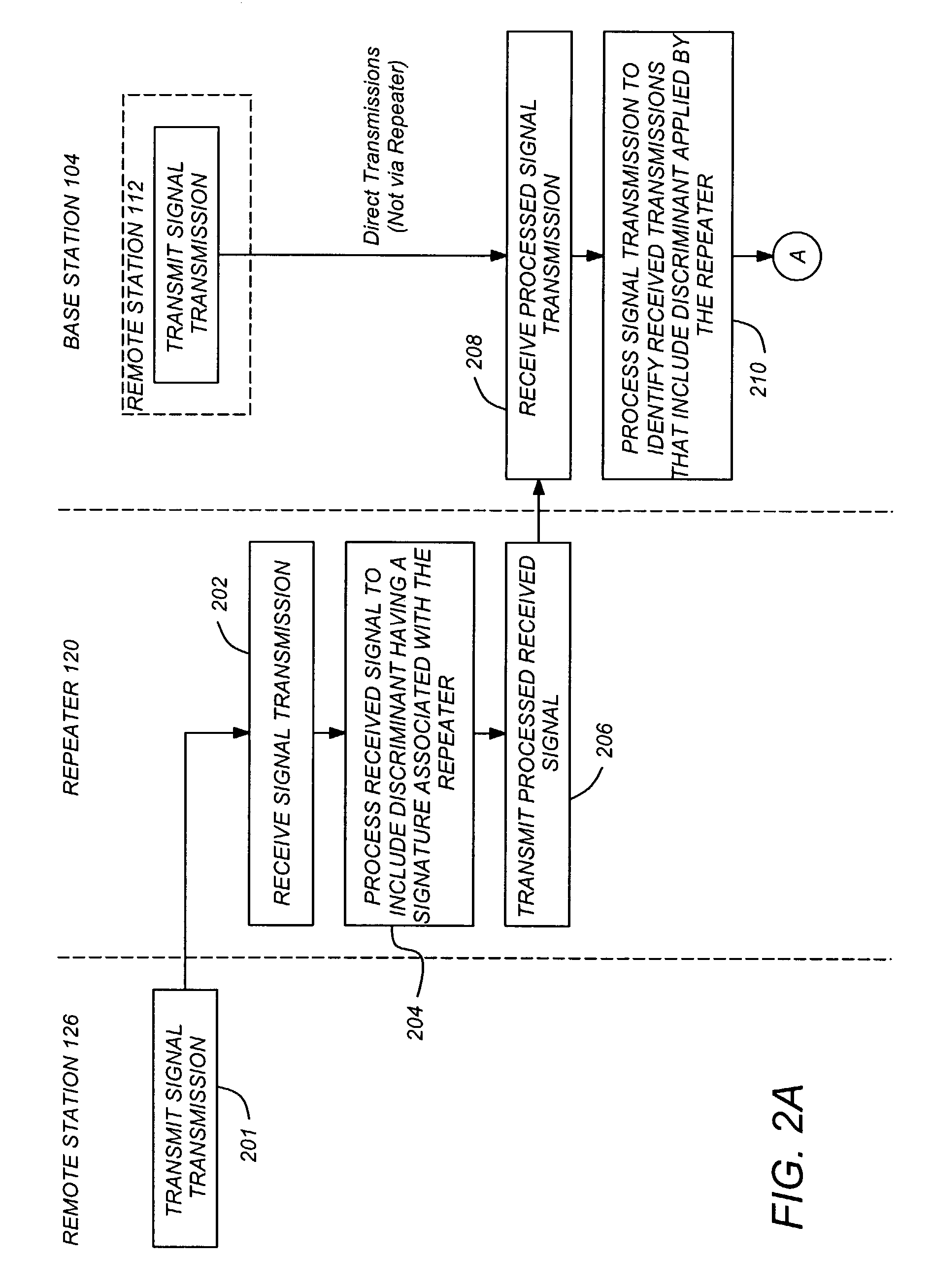
An apparatus and method for identifying remote communications transmitted via a repeater from remote communications not transmitted via the repeater. The method comprises the steps of receiving a plurality of signal transmissions originating from a plurality of remote stations, wherein each of the signal transmissions is associated with a call originating from one of the plurality of remote stations; processing the plurality of received signal transmissions to identify received transmissions that include a discriminant applied by a repeater; and designating each of the plurality of received signal transmissions as being transmitted via the repeater if the received signal transmission includes the discriminant.

Description

CROSS-REFERENCE TO RELATED APPLICATIONS[0001]This application claims benefit of U.S. Provisional Patent Application Ser. No. 60 / 348,198, entitled “METHOD AND SYSTEM FOR IDENTIFYING REPEATER TRAFFIC IN A CDMA MULTIPLE ACCESS SYSTEM,” by Kenneth Robert Baker, filed Jan. 9, 2002, and[0002]This application is also continuation-in-part of the following co-pending and commonly assigned patent application, which application is incorporated by reference herein:[0003]application Ser. No. 10 / 004,177, entitled “METHOD AND SYSTEM FOR IDENTIFYING REPEATER TRAFFIC IN A CODE DIVISION MULTIPLE ACCESS SYSTEM,” filed Oct. 25, 2001, by Kenneth Robert Baker and Brian Butler.BACKGROUND[0004]1. Field of the Invention[0005]The present invention relates to methods and systems for transceiving information between mobile stations and base stations, and in particular to a method and system for determining if a received message was transmitted via a repeater.[0006]2. Description of the Related Art[0007]Cellula...

Claims


Application Information

Patent Timeline
IPC IPC(8): H04B1/60H04B7/14H04B7/15H04L12/26H04W24/00
CPCH04B7/15528H04L43/0876H04L43/0847H04L43/045H04W24/00
Inventor BAKER, KENNETH R.BUTLER, BRIAN K.WHEATLEY, CHARLES E.
Owner QUALCOMM INC
Learn More