Speed-up mode implementation for direct conversion receiver

Inactive Publication Date: 2006-06-13
TEXAS INSTR INC
View PDF15 Cites 11 Cited by
  • Summary
  • Abstract
  • Description
  • Claims
  • Application Information

AI Technical Summary

Benefits of technology

[0012]The gain control input signal can also be employed to implement gain control of one or more amplifiers, such as by imposing delay on the input gain control signal and providing the delayed gain control signal to one or more amplifiers. In a particular aspect of the present invention, the speed-up control signal and signal used to implem

Problems solved by technology

DC offsets are inherent in any amplifier and can arise from sources such as device mismatches.
For example, if the baseband gain is 60 dB, and the input offset on the first amplifier in the baseband is 10 mV, and the supply voltage is 3 V, the output will be limited to the supply, and, if the amplifiers are DC coupled, the receiver would not be able to provide desired l

Method used


Image

  • Speed-up mode implementation for direct conversion receiver
  • Speed-up mode implementation for direct conversion receiver
  • Speed-up mode implementation for direct conversion receiver

Examples


Example

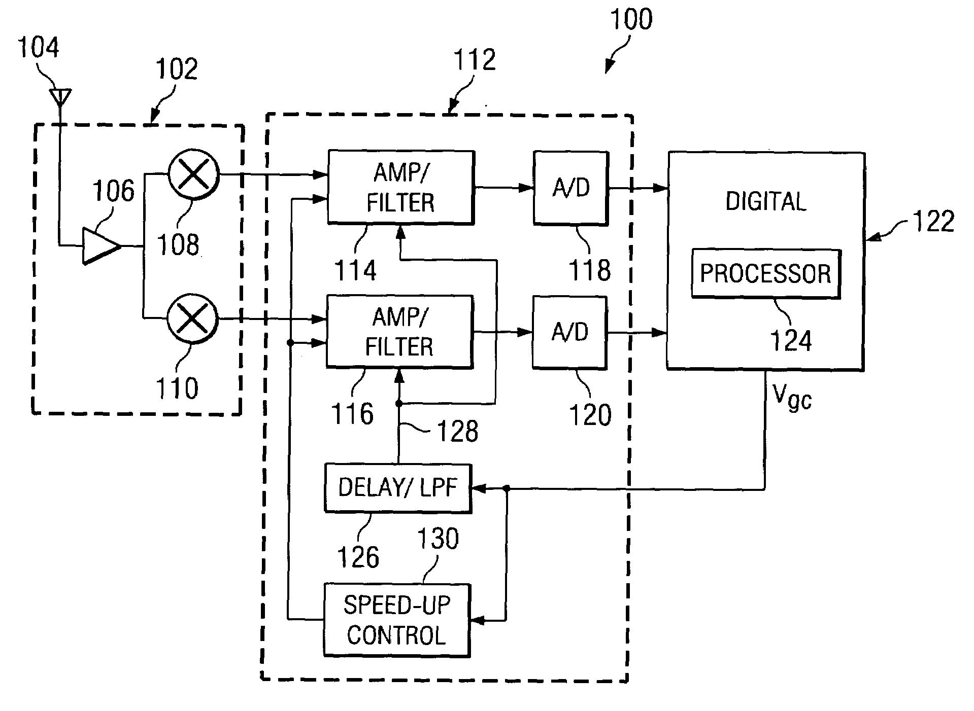
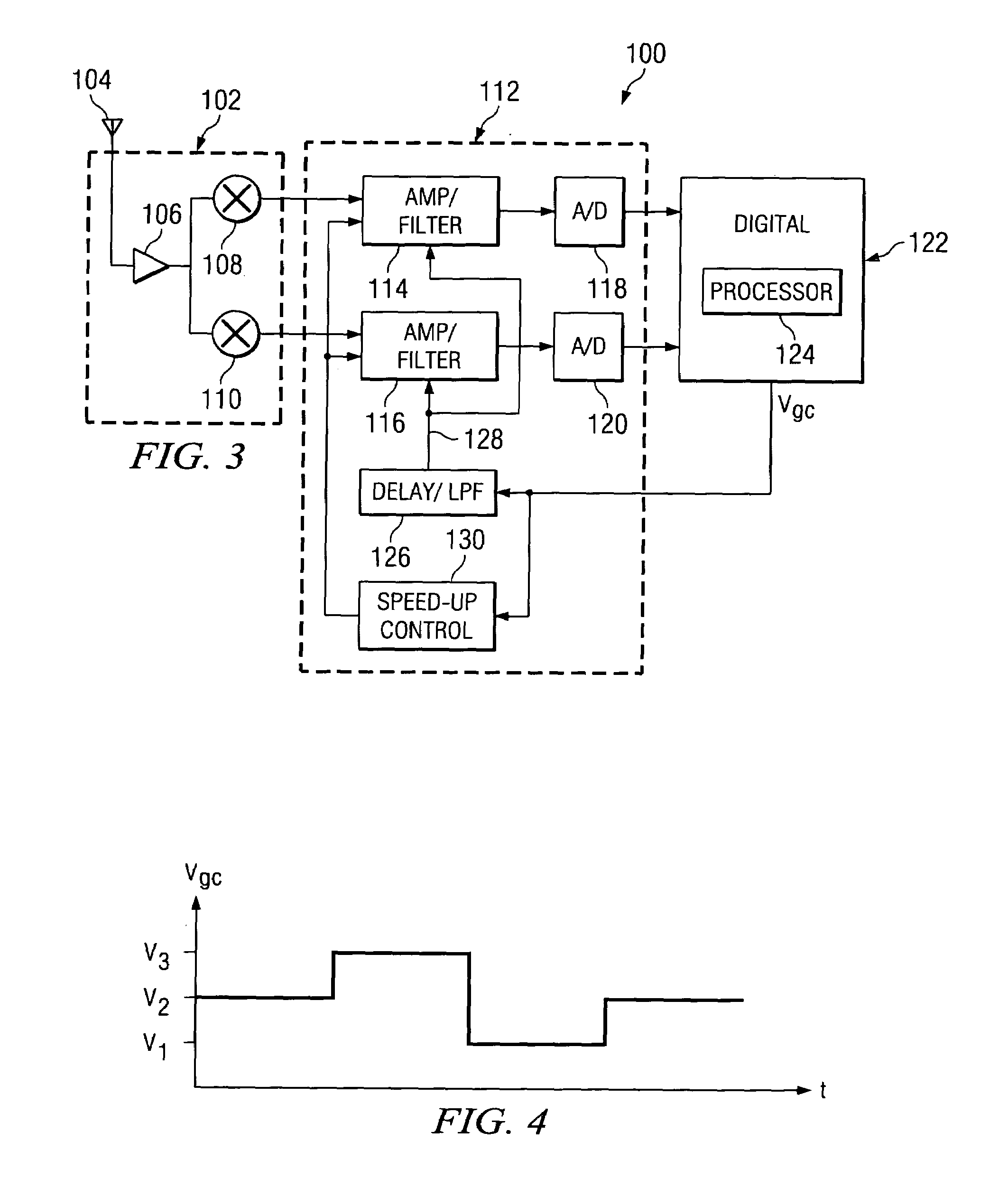
[0023]FIG. 3 illustrates a block diagram of a receiver 100 programmed and / or configured to implement speed-up mode control in accordance with an aspect of the present invention. The receiver 100 includes a receiver front end 102 operative to receive an input RF signal from an associated antenna 104. The receiver front end 102 includes an amplifier / filter network 106 for amplifying the input signal to a desired level and removing unwanted noise. The amplifier / filter network receives an output signal from mixers 108 and 110. Each of the mixers 108 and 110 is associated with a local oscillator (not shown) to mix the filtered input signal with a desired phase shift. For example, the mixers 108 and 110 provide mixed signals that have a relative phase shift of 90 degrees (e.g., quadrature related mixers). By way of illustration, one of the mixed signals can have a 90 phase shift while the other mixed signal has a 0 degree phase shift. Alternatively, one might have a −45 degree phase shift...


PUM


Abstract

A speed-up mode control system is operative to generate a speed-up mode signal based on a gain control signal from associated digital circuitry. The speed-up mode signal controls electronics associated with one or more amplifiers to facilitate settling time of an output signal of the amplifier(s) that occurs when the gain of the amplifier changes. The gain control signal also can be delayed to provide a delayed version of the gain control signal for controlling gain of the amplifier(s).

Description

TECHNICAL FIELD[0001]The present invention relates generally to radio communications and, more particularly, to implementing a speed-up mode for a direct conversion receiver.BACKGROUND OF THE INVENTION[0002]Various approaches exist for receiving and converting an input radio frequency (RF) signal to a desired frequency. Of particular interest are direct conversion receivers. A direct conversion receiver mixes directly to a baseband signal without converting the input RF signal to an intermediate frequency, as is the case in a superheterodyne receiver. That is, a direct conversion receiver converts the incoming radio signal to baseband in a down-conversion step, wherein an associated local oscillator operates at a frequency that coincides with the center of the input RF signal. Direct conversion receivers can be implemented in connection with various communications protocols, such as, for example, the Universal Mobile Telecommunications System (UMTS), General Packet Radio System (GPR...

Claims


Application Information

Patent Timeline
IPC IPC(8): H04B1/06H03G3/20H03G3/30H04B1/30
CPCH03G3/3052H04B1/30H03G3/3078
Inventor GHARPUREY, RANJITYANDURU, NAVEEN K.LITMANEN, PETTERIDANTONI, FRANCESCO
Owner TEXAS INSTR INC
Why Eureka
Try Eureka