Method for determining the B1 field strength in MR measurements

a technology of mr measurement and field strength, applied in the direction of magnetic measurement, instruments, measurement devices, etc., can solve the problems of radio-frequency pulses, number of different techniques already exist, and inability to accurately determine the field strength of radiofrequency pulses

Active Publication Date: 2006-06-20
SIEMENS HEALTHCARE GMBH
View PDF11 Cites 17 Cited by
  • Summary
  • Abstract
  • Description
  • Claims
  • Application Information

AI Technical Summary

Benefits of technology

[0023]An adjustment technique of this sort during the examination to optimize the B1 field strength in a certain volume region of the examination subject is, moreover, basically useful and can be performed, insofar as the data about the B1 field strength distribution within the examination subject can be determined with other techniques, also independently of the measurement technique according to the invention.

Problems solved by technology

Fluctuations in the field strength of the excitation B1 field thus lead to undesired variations in the received magnetic resonance signal which can corrupt the measurement result.
In an unfavorable manner, however, the radio-frequency pulses exhibit particularly in case of high magnetic field strengths—which are necessary due to the required magnetic basic field B0 of currently up to 3 Tesla in an MRT apparatus—an inhomogeneous penetration behavior in conductive and dielectric media such as tissue.
For this purpose, a number of different techniques already exist which, however, are associated with diverse disadvantages in an unfavorable manner.
The disadvantage of such measurements is that the technique can be performed only in layers or slices, i.e. only a certain slice thickness of the volume is excited selectively through suitable switching of the gradient fields during the emission of the pulse.
This is associated with a very long measurement time of approx.
10 minutes and, due to the layer selection, there is an additional flip angle distribution along the layer normals which results in a corresponding measurement error.
This technique again has the disadvantage that only individual layers can be investigated and, particularly in case of in vivo measurements, i.e., measurements inside of the subject, only qualitative evaluations are possible.

Method used


Image

  • Method for determining the B1 field strength in MR measurements
  • Method for determining the B1 field strength in MR measurements
  • Method for determining the B1 field strength in MR measurements

Examples


Embodiment Construction

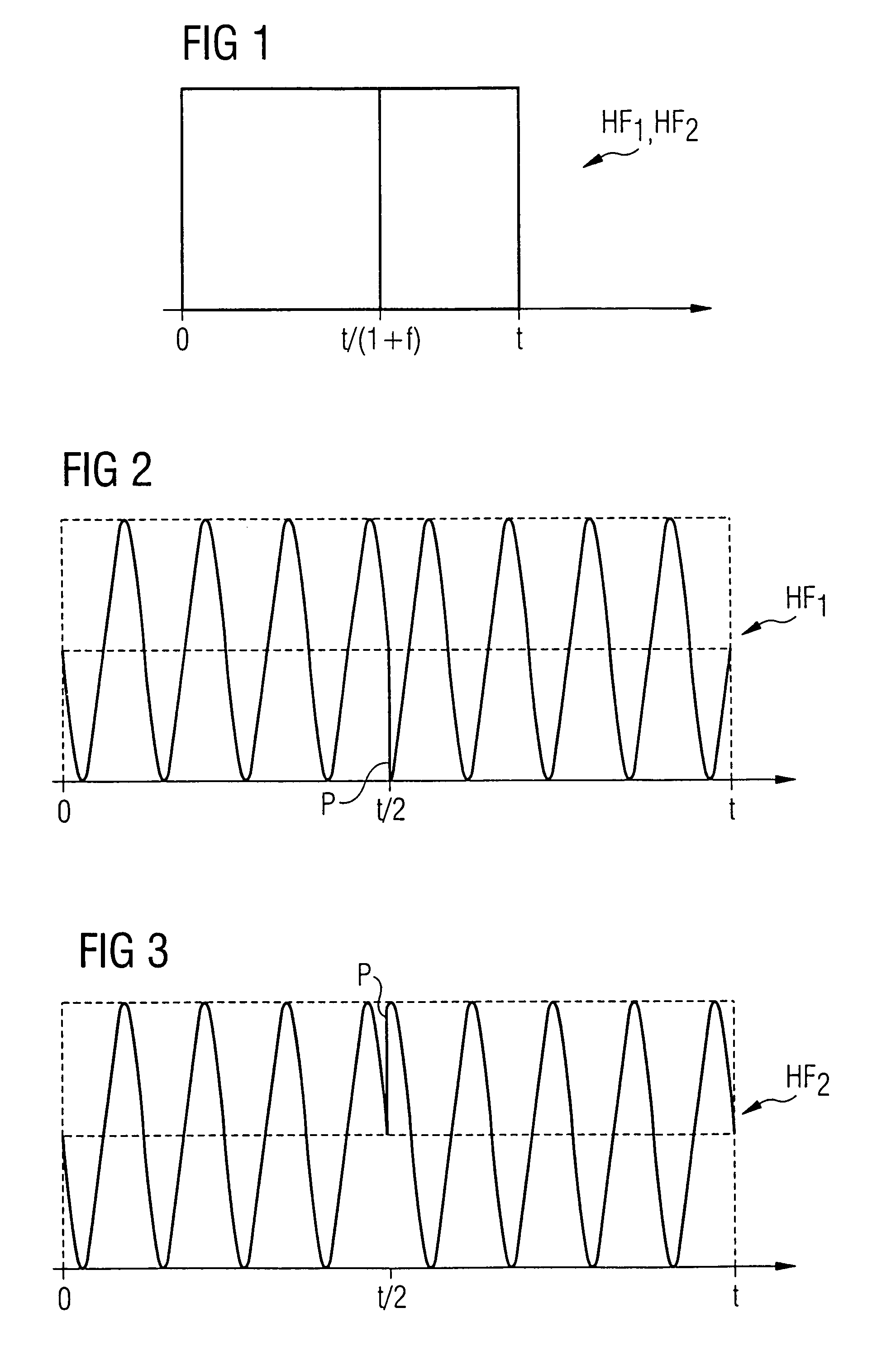
[0038]In order to provide a detailed explanation of the method, it will first be shown how, using simple radio-frequency excitation pulses, a clear relationship is possible between a phase angle of the attained transverse magnetization which can be detected as the phase position of the magnetic resonance signal and the B1 field amplitude. In the present exemplary embodiment, for simplicity—but without restricting the inventive concept—a radio-frequency pulse HF1, HF2 with duration t will be assumed with a rectangular amplitude curve according to FIG. 1. This radio-frequency pulse HF1, HF2 is present from a starting time point 0 up to the time point t / (1+f) with a phase of 0° and afterwards with a phase of 90° (the indications refer to a rotating coordinate system or rather the interaction image). The factor f is a constant factor.

[0039]FIG. 2 shows a special exemplary embodiment for the case in which f=1. The envelope pulse shape of the radio-frequency pulse HF1 corresponds here to ...


PUM


Abstract

In magnetic resonance tomography apparatus and method for determining the field strength of high-frequency pulses which are emitted during a magnetic resonance measurement by the antenna, a magnetic resonance signal excited by a radio-frequency pulse or a radio-frequency pulse sequence is measured, and a phase of the magnetic resonance signal is determined. Based on this phase, the field strength is then determined.

Description

BACKGROUND OF THE INVENTION[0001]1. Field of the Invention[0002]The invention concerns a method for determining the field strength of radio-frequency pulses which are emitted in a magnetic resonance measurement by an antenna of a magnetic resonance measuring device. Moreover, the invention concerns a magnetic resonance measuring device having corresponding arrangement for determining the field strength of emitted radio-frequency pulses[0003]2. Description of the Prior Art[0004]Magnetic resonance tomography (MRT), also known as nuclear spin tomography, has become a widespread technique for obtaining images inside the body of a live examination subject. In order to obtain an image using this technique, the body or the body part being examined of the subject must be exposed to a static basic magnetic field (usually known as the B0 field) which is as homogeneous as possible, the basic magnetic field being generated by a basic field magnet of the magnetic resonance measuring device. Whil...

Claims


Application Information

Patent Timeline
Patent Type & Authority Patents(United States)
IPC IPC(8): G01V3/00G01R33/58
CPCG01R33/583
Inventor FEIWEIER, THORSTEN
Owner SIEMENS HEALTHCARE GMBH
Why Eureka
Try Eureka