
Cross-bar switch supporting implicit multicast addressing

a cross-bar switch and multi-cast addressing technology, applied in the field of routing data, can solve the problems of difficult to meet timing goals and physical design criteria, traditional cross-bar switches consume significant power and circuit space, and achieve the effect of improving memory utilization efficiency and efficient bandwidth allocation managemen

Inactive Publication Date: 2006-06-20
NEXSI SYST +1
View PDF56 Cites 7 Cited by
  • Summary
  • Abstract
  • Description
  • Claims
  • Application Information

AI Technical Summary

Benefits of technology

The present invention is about a non-blocking cross-bar switch that can support multicast addressing and bandwidth allocation management. It uses data rings to connect input and sink ports, allowing multiple data packets to be simultaneously transmitted to different destinations. The switch includes a multiple entry point FIFO for buffering multiple packets, ensuring non-blocking operation. It also regulates bandwidth allocation for each priority level and supports variable packet sizes. The invention can be implemented in hardware or software, and can be used in various systems such as network switches and routers.

Problems solved by technology

Traditional cross-bars employ a large number of switches, making design complex.
The large number of switches makes it difficult to meet timing goals and physical design criteria.
These traditional cross-bars also consume significant power and circuit space.
The disadvantages associated with a traditional cross-bar are particularly troubling when implementing the cross-bar on an integrated circuit.
The blocked data must be resent at a later time—unnecessarily utilizing processing resources and delaying data transfer.
This inflexibility makes multicasting addressing impossible, unless special multicast circuitry is added.
Without multicast addressing, the processing engine performs multiple packet transfers—wasting both processing resources and system bandwidth.
Support for ensuring quality of service is also inefficient in traditional cross-bars.
This is wasteful when one or more data classes are idle—the buffer memories for the idle data classes go unused.
This puts a significant overhead on the system.

Method used


Image

  • Cross-bar switch supporting implicit multicast addressing
  • Cross-bar switch supporting implicit multicast addressing
  • Cross-bar switch supporting implicit multicast addressing

Examples


Embodiment Construction

A. System Employing a Cross-Bar Switch

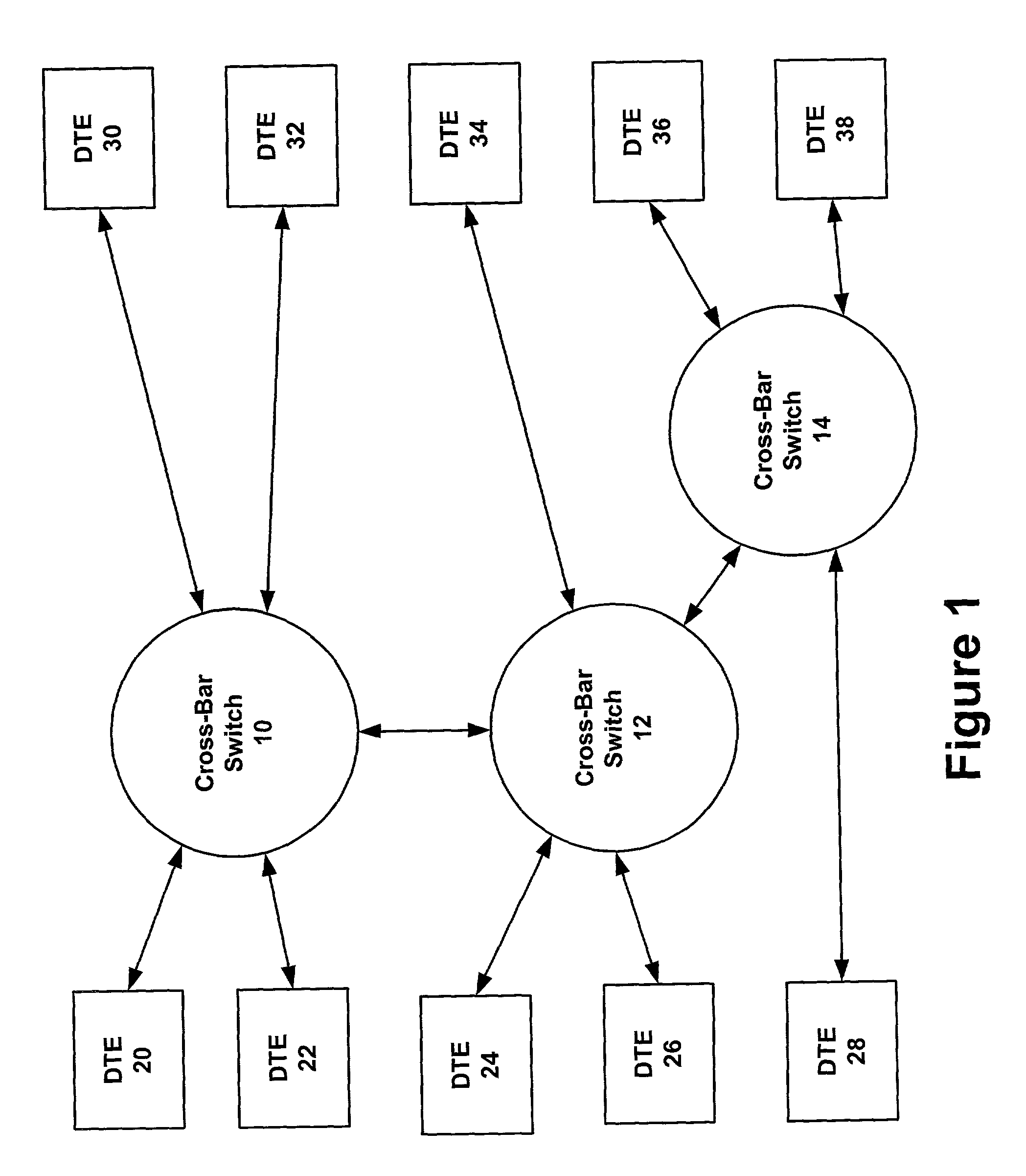
[0039]FIG. 1 illustrates a system employing cross-bar switches 10, 12, and 14, which operate in accordance with the present invention. Cross-bar switch 10 is coupled to transfer packets between cross-bar switch 12 and data terminal equipment (“DTE”) 20, 22, 30 and 32. Cross-bar switch 12 is coupled to transfer packets between cross-bar switches 10 and 14 and DTE 24, 26, and 34. Cross-bar switch 14 is coupled to transfer packets between cross-bar switch 12 and DTE 28, 36, and 38.

[0040]DTE is a generic name for a computing system including a processing engine, ranging from a complex multi-processor computer system to a stand-alone processing engine. At least one example of a DTE is multi-processor unit 10 described in U.S. patent application Ser. No. 09 / 900,481, entitled Multi-Processor System, filed on Jul. 6, 2001, and hereby incorporated by reference.

[0041]In one embodiment, all of the elements appearing in FIG. 1 reside in the same system and ...


PUM


Abstract

A cross-bar switch includes a set of input ports and a set of sink ports in communication with the input ports. The input ports receive packets, which are snooped by the sink ports. The cross-bar switch also includes a set of port address tables. Each port address table is adapted to store data identifying a plurality of destinations supported by a sink port. For example, a first port address table is adapted to identify a plurality of destinations supported by a first sink port in the set of sink ports. When determining whether to accept a packet, a sink port considers whether the packet's destination is identified in the sink port's port address table. By supporting multiple destinations, a port address table implicitly facilitates a sink port's multicast operation.

Description

[0001]This application claims the benefit of and is a continuation of U.S. patent application Ser. No. 09 / 900,514, “Cross-Bar Switch,” filed on Jul. 6, 2001, which is incorporated herein by reference.CROSS-REFERENCE TO RELATED APPLICATIONS[0002]This Application is related to the following amended section:[0003]“Cross-Bar Switch With Explicit Multicast Support,” by Abbas Rashid, Mark Bryers, and Nazar Zaidi, U.S. patent application Ser. No. 10 / 036,602, filed the same day as the present application;[0004]“Cross-Bar Switch Incorporating A Sink Port With Retry Capability,” by Mark Bryers, Abbas Rashid, and Nazar Zaidi, U.S. patent application Ser. No. 10 / 036,762, filed the same day as the present application; and[0005]“Cross-Bar Switching Employing A Multiple Entry Point FIFO,” by Abbas Rashid and Nazar Zaidi, U.S. patent application Ser. No. 10 / 036,622, filed the same day as the present application; and[0006]“Cross-Bar Switch With Bandwidth Allocation,” by Mark Bryers, Fred Gruner, Abb...

Claims


Application Information

Patent Timeline
Patent Type & Authority Patents(United States)
IPC IPC(8): H04L12/56H04L12/28H04L12/24H04L12/42
CPCH04L12/42H04L41/0896H04L49/101H04L49/25H04L49/102H04L49/3018H04L49/201H04L49/205
Inventor RASHID, ABBASZAIDI, NAZARBRYERS, MARK
Owner NEXSI SYST
Learn More