Image processing method and apparatus

Inactive Publication Date: 2006-06-20
TOYOTA CENT RES & DEV LAB INC
View PDF27 Cites 35 Cited by
  • Summary
  • Abstract
  • Description
  • Claims
  • Application Information

AI Technical Summary

Benefits of technology

[0048]In image processing for processing an image captured by a camera mounted on a vehicle, a lane mark on a road surface or an obstacle on a road is detected, and in such a case, an edge is generally extracted as a feature. In image processing for outdoor scenes, a camera equipped with an AGC function is used as an image capturing means in order to cope with variation in brightness such as variation between day and night. The noise level of an image captured at a dark place or at night is high, because the amplification factor is increased by the AGC. When such an image of high noise level is subjected to the same image processing as that employed for images captured at a bright place or in the daytime, a problem may occur. In the case of lane mark detection, a noise component is detected as an edge and is handled as a candidate of the lane mark. In such a case, the noise level measurement means of the image processing apparatus of the present invention measures the noise level of the original signal accurately and efficiently, and outputs the results to the control means. On the basis of the measurement results, the control means adjusts a threshold value which is used for binarization of the edge. Alternatively, the control means increases the degree of suppression of noise. This enables extraction of a feature without influence of image noise. By virtue of the above configuration, image processing can be performed more properly, without influence of image noise, for an image of high noise level such as an image captured at night.
[0049]Moreover, the present invention prov

Problems solved by technology

When an image having both shady and sunny regions; i.e., an image having great contrast, is captured and displayed on a display unit having a narrow dynamic range of brightness, a dark portion of the image is displayed as a solid black region and a bright portion is displayed as a solid white region, thereby rendering an object or the like within the image difficult to discern.
However, there arises a problem in that contrasts in the remaining luminance ranges decrease.
For example, when Homomorphic Filtering is applied to an image including a traffic control measure on a road, such as a lane mark or a pedestrian crossing, the traffic control measure is displayed as a grayish image, which in some cases is extremely difficult to recognize.
In the case of employment of a simplified method of suppressing a low spatial frequency component as measured along a single direction such as a vertical direction or a horizontal direction, the above-described problem becomes remarkable.
This image conversion process provides an image that imparts an extremely unnatural impression.
For the same reason, a low frequency component of low luminance may become brighter in some cases; however, this provides an unnatural impression to a lower degree as compared to the case of a white object being displayed as a gray obj

Method used


Image

  • Image processing method and apparatus
  • Image processing method and apparatus
  • Image processing method and apparatus

Examples


first embodiment

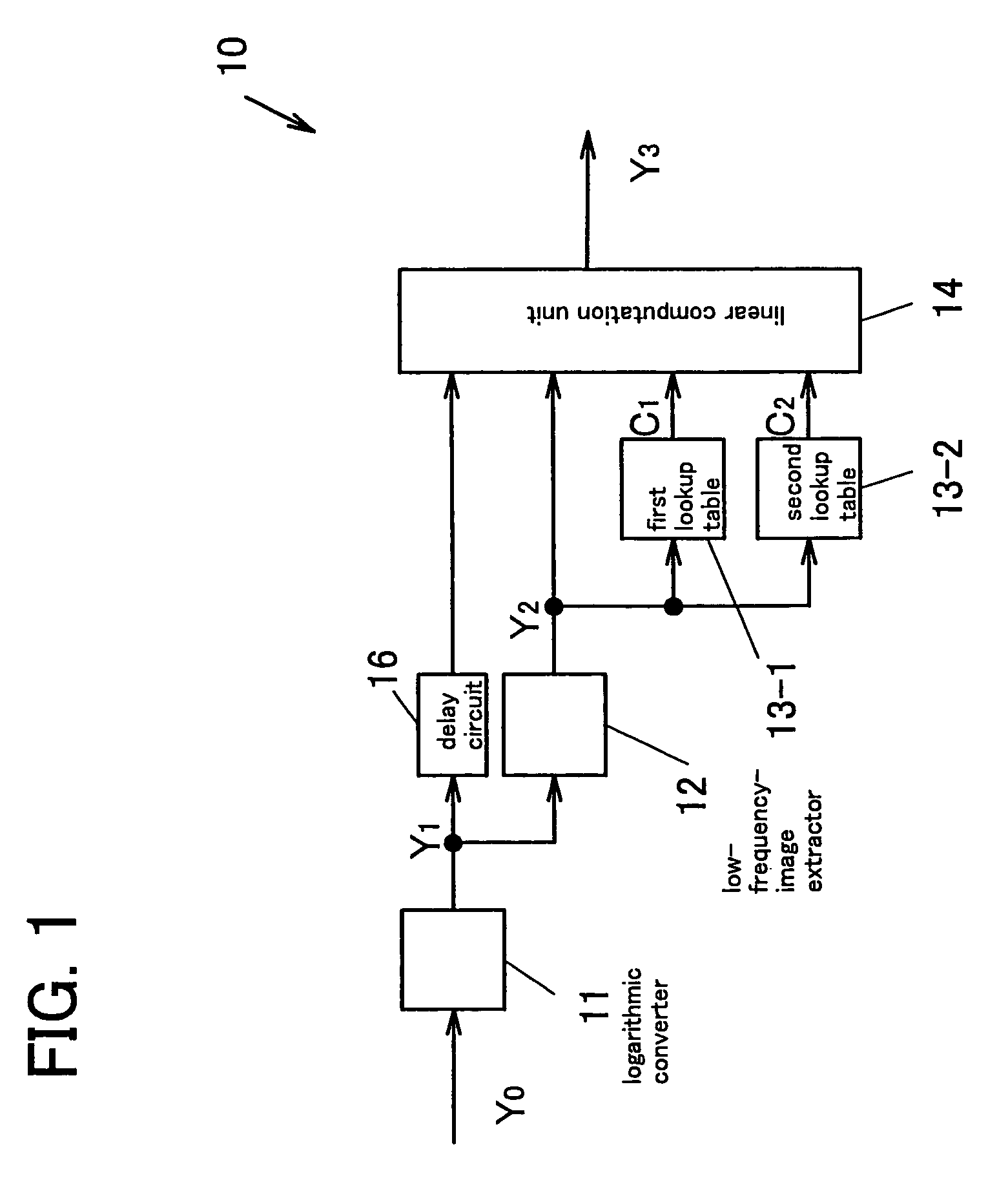
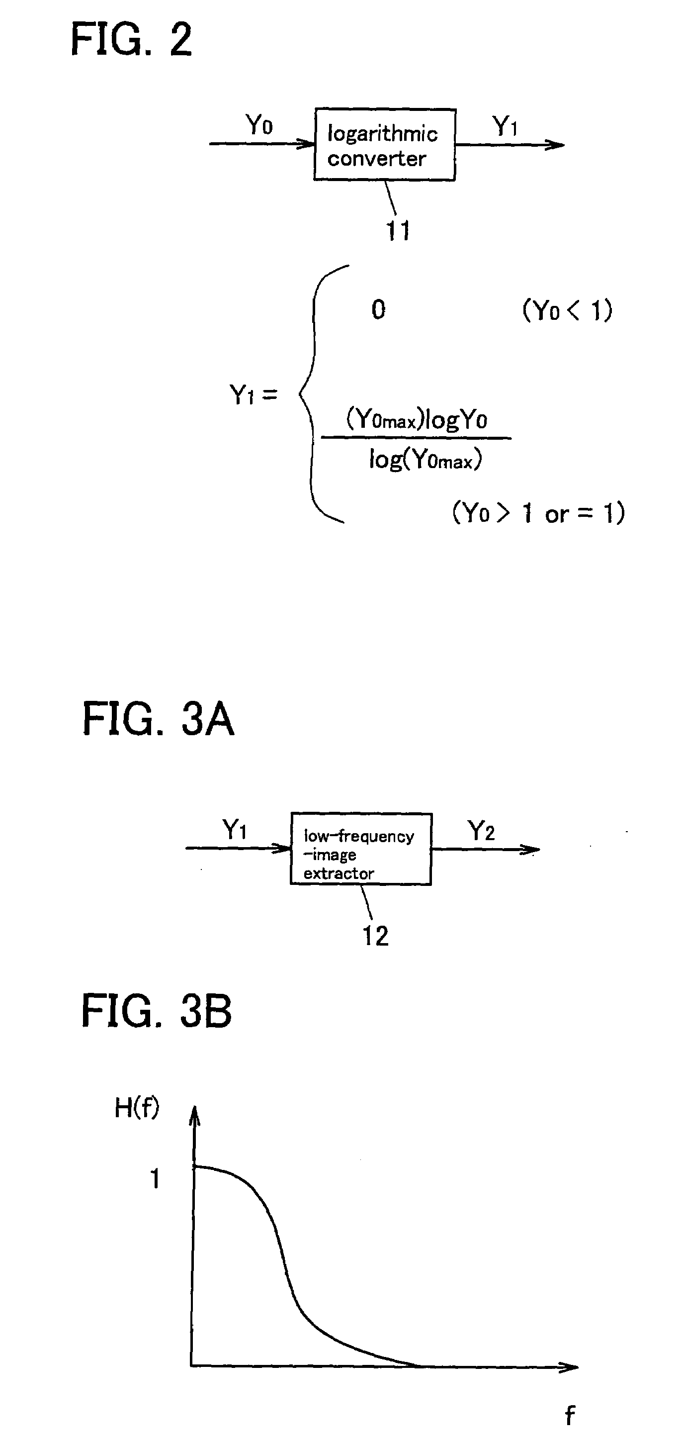
[0081]FIG. 1 is a block diagram showing the configuration of an image conversion apparatus 10 according to a first embodiment of the present invention. The image conversion apparatus 10 includes a logarithmic converter 11, a low-frequency-image extractor 12, a delay circuit 16, a first lookup table 13-1, a second lookup table 13-2, and a linear computation unit 14. The low-frequency-image extractor 12 corresponds to the low-frequency-image extraction means; the first lookup table 13-1 and the second lookup table 13-2 correspond to the first and second coefficient determination means, respectively; and the linear computation unit 14 corresponds to the linear computation means. In the present embodiment, the inverse logarithmic conversion 93 shown in FIG. 18 is not used. The image conversion apparatus 10 of the present embodiment is of a high-speed type which performs frequency filtering on a line-by-line basis. Note that in the present embodiment, the constituent elements of the imag...

second embodiment

[0091]FIG. 6 is a block diagram showing the configuration of an image conversion apparatus 20 according to a second embodiment of the present invention. The image conversion apparatus 20 can be obtained by adding a gradation converter 15 to the image conversion apparatus 10 of the first embodiment. The gradation converter 15 performs gray-scale modification processing for luminance Y3 of the converted image, which is the output of the linear computation unit 14, to thereby obtain luminance Y4. The gradation converter 15 may be constituted by a lookup table.

[0092]The gray-scale modification performed by the gradation converter 15 will be described with reference to FIGS. 7 to 9C. FIG. 7 shows the manner of compression of the dynamic range of the low frequency component of luminance Y3 of the converted image, which is the output of the linear computation unit 14. Specifically, FIG. 7 is a graph showing the relation between luminance Y2 of the low frequency image and luminance Y3 of th...

third embodiment

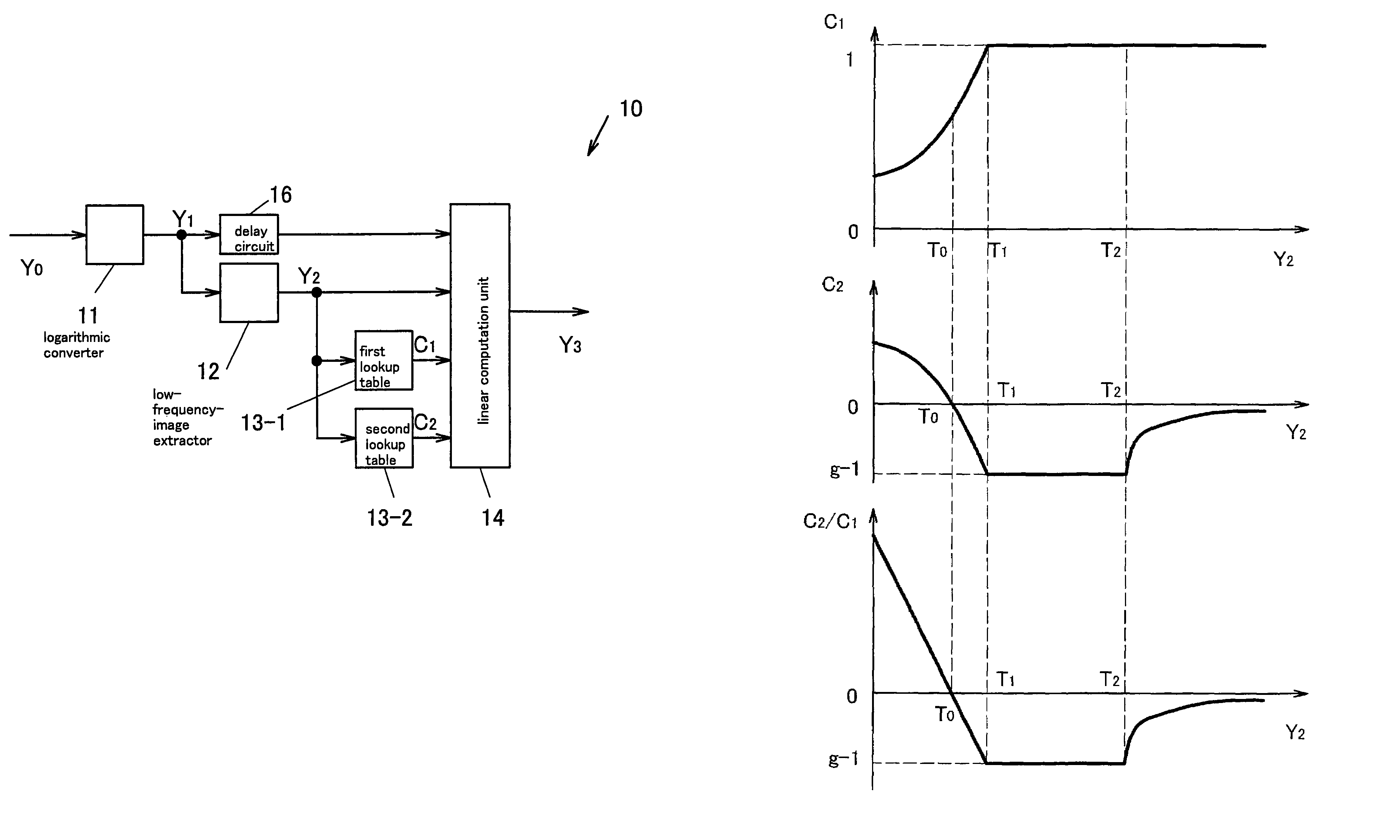
[0095]The first embodiment can be modified to use the following as the coefficients C1 and C2, each of which is a function of luminance Y2 of the low frequency image.

[0096]Expression⁢⁢2⁢:C1={g⁡(T1-T0)(g-1)⁢(Y2-T0)+T1-T0⁢(Y2≤T1)⁢1⁢(Y2≥T1)⁢⁢C2={g⁡(g-1)⁢(Y2-T0)(g-1)⁢(Y2-T0)+T1-T0⁢(Y2≤T1)⁢g-1(T1≤Y2≤T2)⁢(1-g)⁢(Y2⁢max-Y2)γγ⁡(Y2⁢max-T2)γ-1⁢Y2+(g-1)⁢{(γ-1)⁢T2+Y2⁢max}γ⁢⁢Y2⁢(Y2≥T2)

[0097]In Expression 2, Y2max represents the maximum value that Y2 can assume, and γ represents a constant not less than 1. Expression 2 is formulated in such a manner that luminance Y3 is considered to be obtained by the expression Y3=C1Y1+C2Y2=C1(Y1+C2Y2 / C1) and that the derivative of C2 Y2 / C1 with respect to Y2 becomes continuous. When C1 is constant, the derivative of C2Y2 / C1 with respect to Y2 having had its sign inverted is the dynamic range compression ratio. Therefore, the dynamic range compression ratio for luminance Y2 can be changed continuously. In actuality, the coefficients C1 and C2 are continuous, and...


PUM


Abstract

In an image conversion method and apparatus, luminance Y3 of each pixel of a converted image is obtained by use of an expression Y3=C1Y1+C2Y2 and from luminance Y1 of a corresponding pixel of a source image, luminance Y2 of a corresponding pixel of a low frequency image, and C1 and C2 which are functions of the luminance Y2. Since C1+C2 is constant when Y2≦T2, contrast of a low frequency component can be prevented from decreasing. In a portion in which the luminance Y2 of the low frequency image is low, the low frequency image is enhanced. In a portion in which the luminance Y2 of the low frequency image is high, the low frequency image is suppressed. In a method and apparatus for detecting noise level of an original signal in real time, a plurality of local regions are set on an input image in such a manner that the local regions are distributed uniformly over the entire area of an image. In each local region, determination as to whether or not luminance is saturated is performed. Variation in luminance is detected in each of a plurality of unsaturated local regions. Noise level is determined on the basis of the detected variation.

Description

[0001]This is a patent application based on Japanese patent application Nos. 2001-265895 and 2002-137779, which were filed on Sep. 3, 2001 and May 13, 2002, respectively, and which are incorporated herein by reference.BACKGROUND OF THE INVENTION[0002]1. Field of the Invention[0003]The present invention relates to an image conversion method and apparatus for compressing the dynamic range of brightness of an image in which each pixel has a luminance value representing the density thereof. Note that in the present specification, the expression “spatial frequency” of luminance of a two-dimensional image encompasses the single-dimensional luminance frequency for each line (for each row or each column).[0004]The present invention also relates to a noise detection method for detecting noise contained in an original signal and to an image processing apparatus utilizing the method. In particular, the present invention relates a noise detection method in which a plurality of local regions are...

Claims


Application Information

Patent Timeline
IPC IPC(8): G06K9/40H04N1/21
CPCH04N1/2112
Inventor SOGA, MINEKIYAMADA, KEIICHIOHTA, MITSUHIKO
Owner TOYOTA CENT RES & DEV LAB INC
Why Eureka
Try Eureka