High speed rotor assembly shroud

a rotor assembly and high-speed technology, applied in the field of rotor blade shrouds, can solve the problems of increasing the centrifugal bending stress of the shroud during operation, reducing the thickness of the shroud, etc., and achieves the effects of reducing the centrifugal stress on the blade, reducing the mass, and improving strength

Active Publication Date: 2006-06-27
THE BOEING CO
View PDF10 Cites 10 Cited by
  • Summary
  • Abstract
  • Description
  • Claims
  • Application Information

AI Technical Summary

Benefits of technology

[0012]The present invention addresses the above needs and achieves other advantages by providing a rotor assembly blade having a shroud with a lower mass than conventional shrouds, thereby reducing the centrifugal stress on the blade, and with improved strength, thereby reducing the centrifugal bending stress on the shroud.
[0013]In one embodiment, the present invention includes a shroud with a constant thickness. By maintaining a constant thickness, the shroud mass may be advantageously reduced relative to conventional shrouds, thereby reducing the centrifugal stress on the blade during operation. However, the reduction in shroud thickness increases the centrifugal bending stress on the shroud during operation. To provide sufficient strength to withstand the centrifugal bending stress on the shroud during operation, the shroud includes one or more reinforcing flanges on the upper surface of the lower portion of the shroud. The reinforcing flange or flanges may include a sealing rail extending radially outwardly therefrom to prevent the leakage of working fluid through the shroud-housing gap.
[0014]In another embodiment of the present invention, the shroud mass is advantageously reduced further by tapering the leading and trailing edges of the shroud in a circumferential direction such that a width of the lower portion between opposed first and second circumferential sides varies in the circumferential direction.
[0015]In yet another aspect of the present invention, the shroud mass is further advantageously reduced for shroud designs that incorporate blade-to-blade dampers by providing a shroud damper cavity in which the damper cavity inner diameter surface defines an opening therethrough having a narrow ledges to retain the damper against gravitational forces during non-rotation of the rotor assembly. This configuration effectively retains a blade-to-blade damper but eliminates the additional mass of a shroud damper cavity with an intact inner diameter surface.

Problems solved by technology

However, the reduction in shroud thickness increases the centrifugal bending stress on the shroud during operation.

Method used


Image

  • High speed rotor assembly shroud
  • High speed rotor assembly shroud
  • High speed rotor assembly shroud

Examples


Embodiment Construction

[0025]The present invention now will be described more fully with reference to the accompanying drawings, in which preferred embodiments of the invention are shown. This invention may, however, be embodied in many different forms and should not be construed as limited to the embodiments set forth herein; rather, these embodiments are provided so that this disclosure will be thorough and complete, and will fully convey the scope of the invention to those skilled in the art. Like numbers refer to like elements throughout.

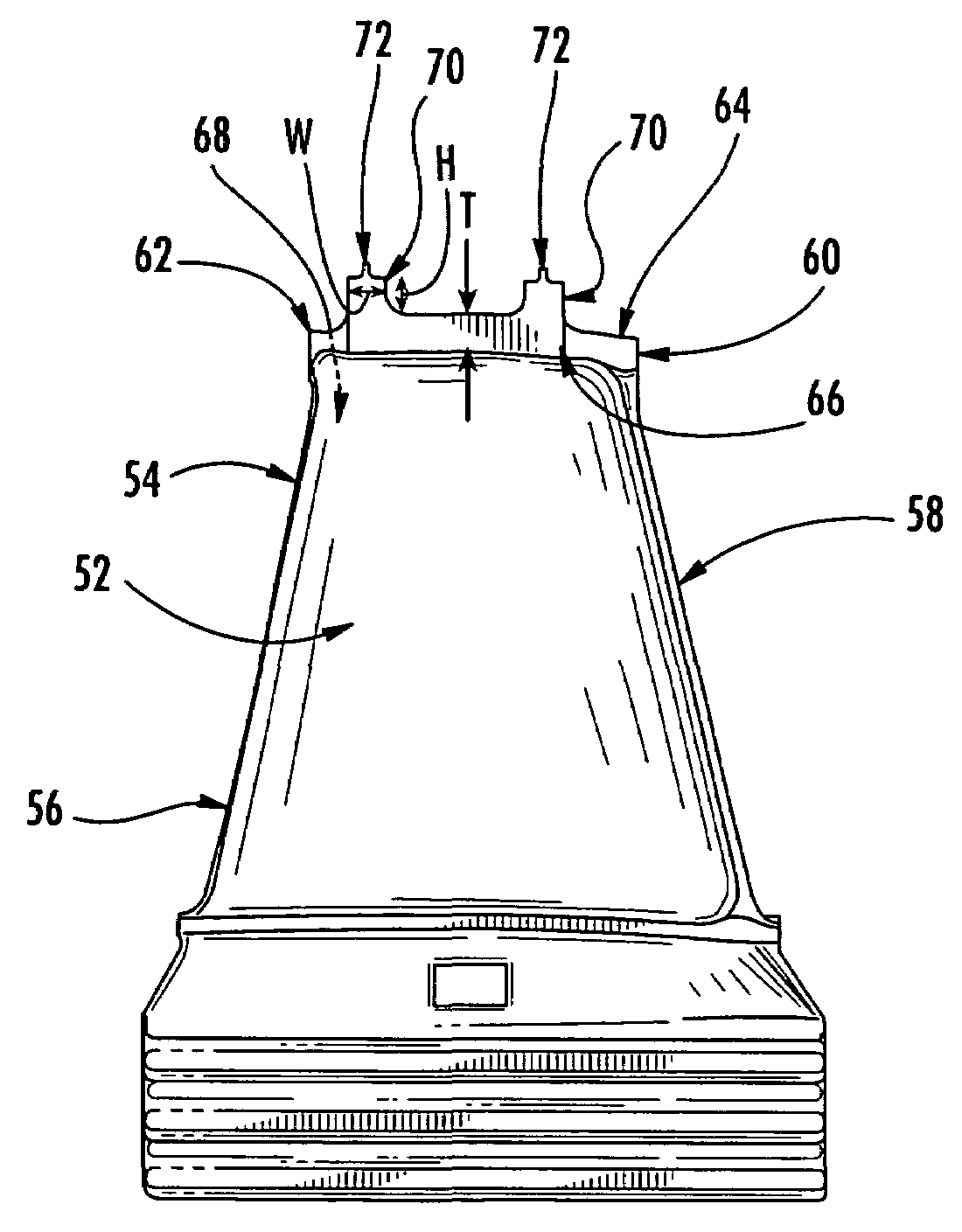
[0026]FIG. 4 illustrates a rotor blade incorporating a shroud of one embodiment of the present invention. The airfoil portion of the rotor blade includes a generally concave high-pressure sidewall 52 and a generally convex low-pressure sidewall 54 that extend axially from the blade leading edge 56 to the blade trailing edge 58. The shroud has a lower portion 60 with a constant thickness, T, defined by the distance between its upper surface and opposing lower surface, ...


PUM


Abstract

An improved rotor assembly shroud includes at least one reinforcing flange on the upper surface of the shroud. The strength provided by the reinforcing flange allows for a smaller shroud thickness resulting in a net reduction of shroud mass. The lower shroud mass reduces the centrifugal stress on the rotor assembly blade during operation. The strength provided by the reinforcing flanges also significantly reduces the centrifugal bending stress on the shroud during operation. The shroud mass may be further reduced by tapering the shroud leading and trailing edges or, for shrouds incorporating a damper, by providing a damper cavity with a lower diameter surface defining an opening therethrough.

Description

FEDERALLY SPONSORED RESEARCH OR DEVELOPMENT[0001]The invention described herein was made in the performance of work under NASA Contract No. NAS8-01107 and is subject to the provisions of Section 305 of the National Aeronautics and Space Act of 1958 (72 Stat. 435; 42 U.S.C. 2457).BACKGROUND OF THE INVENTION[0002]1. Field of the Invention[0003]This invention relates to rotor blade shrouds and more specifically to reducing centrifugal stresses experienced by rotor blade components during operation.[0004]2. Description of Related Art[0005]Rotor assemblies are used in a variety of turbo-machines, such as turbines, compressors and the like. Regardless of the application, as shown in FIG. 1, typical rotor assembly 2 construction includes a disk 4 mounted on a rotating shaft 6 with a plurality of blades 8 extending radially outward around the circumference of the disk. The blades are normally mounted on the disk in a dovetail slot 9 designed to match the dovetail root portion 10 of the blad...

Claims


Application Information

Patent Timeline
Patent Type & Authority Patents(United States)
IPC IPC(8): F04D29/08F01D5/22F03B3/12
CPCF01D5/225F05D2300/702Y02T50/671Y02T50/60
Inventor MILLER, JEFF H.ZHENG, XINHONG J.GROTA, STEVEN P.PHUI, KHIN C.
Owner THE BOEING CO
Why Eureka
Try Eureka