Selective organ cooling apparatus and method

a technology for organs and cooling apparatuses, applied in the field of selection and control of the temperature of selected body organs, can solve the problems of low cardiac output, severe derangement of the cardiovascular system, and risk of systematic vascular effects of use of total body hypothermia, and achieve the effects of enhancing surface area, and increasing turbulence or mixing

Inactive Publication Date: 2006-06-27
ZOLL CIRCULATION
View PDF413 Cites 4 Cited by
  • Summary
  • Abstract
  • Description
  • Claims
  • Application Information

AI Technical Summary

Benefits of technology

[0015]In one embodiment, the turbulence-inducing or mixing-inducing exterior surfaces of the heat transfer element comprise one or more alternating ridges and grooves. The ridges and grooves can be aligned longitudinally along the heat transfer element, or they can be arranged helically around the heat transfer element. Where straight ridges and grooves are used, adjacent segments can have their ridges angularly offset from each other, to increase turbulence or mixing. Similarly, where helical ridges are used, adjacent segments of the heat transfer element can be oppositely spiraled, to increase turbulence or mixing. For instance, the first elongated heat transfer segment may comprise one or more helical ridges having a counter-clockwise twist, while the second elongated heat transfer segment comprises one or more helical ridges having a clockwise twist. Alternatively, of course, the first elongated heat transfer segment may comprise one or more clockwise helical ridges, and the second elongated heat transfer segment may comprise one or more counter-clockwise helical ridges. The first and second elongated, articulated segments may be formed from highly conductive materials, such as a metal, or a polymer doped or loaded with particles or filaments of a conductive material. Where the surface has sufficiently pronounced features such as ridges, the enhanced surface area alone may provide sufficient heat transfer, without a need for angular offsets, or opposite spirals, to induce turbulence or mixing.

Problems solved by technology

Cerebral hypothermia has traditionally been accomplished through whole body cooling to create a condition of total body hypothermia in the range of 20° C. to 30° C. However, the use of total body hypothermia risks certain deleterious systematic vascular effects.
For example, total body hypothermia may cause severe derangement of the cardiovascular system, including low cardiac output, elevated systematic resistance, and ventricular fibrillation.
Other side effects include renal failure, disseminated intravascular coagulation, and electrolyte disturbances.
In addition to the undesirable side effects, total body hypothermia is difficult to administer.
However, use of the Dato device implicates the negative effects of total body hypothermia described above.
However, such methods rely on conductive heat transfer through the skull and into the brain.
One drawback of using conductive heat transfer is that the process of reducing the temperature of the brain is prolonged.
Also, it is difficult to precisely control the temperature of the brain when using conduction due to the temperature gradient that must be established externally in order to sufficiently lower the internal temperature.
In addition, when using conduction to cool the brain, the face of the patient is also subjected to severe hypothermia, increasing discomfort and the likelihood of negative side effects.
It is known that profound cooling of the face can cause similar cardiovascular side effects as total body cooling.
From a practical standpoint, such devices are cumbersome and may make continued treatment of the patient difficult or impossible.
However, external circulation of blood is not a practical approach for treating humans because the risk of infection, need for anticoagulation, and risk of bleeding is too great.
Further, this method requires cannulation of two vessels making it more cumbersome to perform particularly in emergency settings.
Even more, percutaneous cannulation of the carotid artery is difficult and potentially fatal due to the associated arterial wall trauma.
Finally, this method would be ineffective to cool other organs, such as the kidneys, because the feeding arteries cannot be directly cannulated percutaneously.
Perfusion of a cold solution has a number of drawbacks, including a limited time of administration due to excessive volume accumulation, cost, and inconvenience of maintaining the perfusate and lack of effectiveness due to the temperature dilution from the blood.
Temperature dilution by the blood is a particular problem in high blood flow organs such as the brain.

Method used


Image

  • Selective organ cooling apparatus and method
  • Selective organ cooling apparatus and method
  • Selective organ cooling apparatus and method

Examples


second embodiment

[0083]FIG. 8 is a cut-away perspective view of a heat transfer element 50. An external surface 52 of the heat transfer element 50 is covered with a series of axially staggered protrusions 54. The staggered nature of the outer protrusions 54 is readily seen with reference to FIG. 9 which is a transverse cross-sectional view taken at a location denoted by the line 9—9 in FIG. 8. If desired, the height, dp, of the staggered outer protrusions 54 can be greater than the thickness of the boundary layer which would develop if a smooth heat transfer element had been introduced into the blood stream. As the blood flows along the external surface 52, it collides with one of the staggered protrusions 54 and a turbulent wake flow is created behind the protrusion. As the blood divides and swirls along side of the first staggered protrusion 54, its turbulent wake encounters another staggered protrusion 54 within its path preventing the re-lamination of the flow and creating yet more turbulence. I...

third embodiment

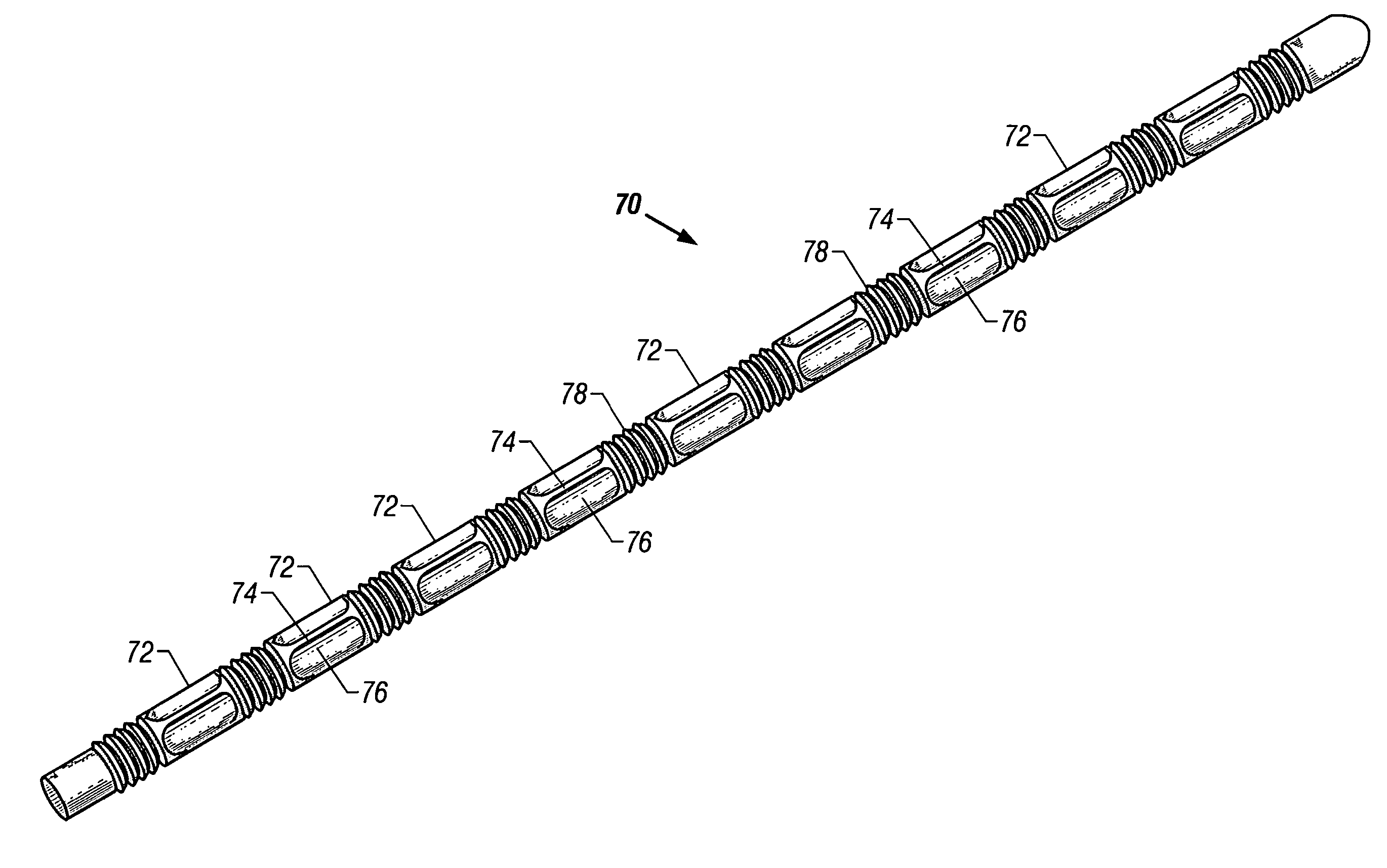
[0090]FIG. 11 is a perspective view of a heat transfer element 70 according to the present invention. The heat transfer element 70 is comprised of a series of elongated, articulated segments or modules 72. A first elongated heat transfer segment 72 is located at the proximal end of the heat transfer element 70. The segment 72 may be a smooth right circular cylinder, as addressed in FIG. 3C, or it can incorporate a turbulence-inducing or mixing-inducing exterior surface. The turbulence-inducing or mixing-inducing exterior surface shown on the segment 72 in FIG. 11 comprises a plurality of parallel longitudinal ridges 74 with parallel longitudinal grooves 76 therebetween. One, two, three, or more parallel longitudinal ridges 74 could be used without departing from the spirit of the present invention. In the embodiment where they are used, the longitudinal ridges 74 and the longitudinal grooves 76 of the heat transfer segment 72 are aligned parallel with the axis of the first heat tran...

fourth embodiment

[0094]FIG. 12 is a perspective view of a heat transfer element 80 according to the present invention. The heat transfer element 80 is comprised of a series of elongated, articulated segments or modules 82. A first elongated heat transfer segment 82 is located at the proximal end of the heat transfer element 80. A turbulence-inducing or mixing-inducing exterior surface of the segment 82 comprises a plurality of parallel longitudinal ridges 84 with parallel longitudinal grooves 86 therebetween. One, two, three, or more parallel longitudinal ridges 84 could be used without departing from the spirit of the present invention. In this embodiment, the longitudinal ridges 84 and the longitudinal grooves 86 of the heat transfer segment 82 are aligned parallel with the axis of the first heat transfer segment 82.

[0095]The first heat transfer segment 82 is coupled to a second elongated heat transfer segment 82 by a first flexible section such as a bellows section 88, which provides flexibility ...


PUM


Abstract

An endovascular heat transfer device which can have a smooth exterior surface, or a surface with ridges and grooves. The device can have a plurality of elongated, articulated segments, with each having such a surface. A flexible joint connects adjacent elongated, articulated segments. The flexible joints can be bellows or flexible tubes. An inner lumen is disposed within the heat transfer segments. The inner lumen is capable of transporting a pressurized working fluid to a distal end of the heat transfer element.

Description

CROSS REFERENCE TO RELATED APPLICATIONS[0001]This is a continuation patent application of U.S. patent application Ser. No. 10 / 161,107, filed on May 30, 2002, and entitled “Selective Organ Cooling Apparatus and Method” now U.S. Pat. No. 6,702,842; which is a continuation patent application of U.S. patent application Ser. No. 09 / 607,799, filed on Jun. 30, 2000, and entitled “Selective Organ Cooling Apparatus and Method” now U.S. Pat. No. 6,464,716; which is a continuation-in-part patent application of U.S. patent application Ser. No. 09 / 570,075, filed on May 12, 2000, and entitled “Selective Organ Cooling Apparatus and Method” now U.S. Pat. No. 6,471,717; a continuation-in-part patent application of U.S. patent application Ser. No. 09 / 215,041, filed on Dec. 16, 1998, and entitled “Articulation Device for Selective Organ Cooling Apparatus”, now U.S. Pat. No. 6,254,626; a continuation-in-part patent application of U.S. patent application Ser. No. 09 / 103,342, filed on Jun. 23, 1998, and ...

Claims


Application Information

Patent Timeline
Patent Type & Authority Patents(United States)
IPC IPC(8): A61F7/00A61B17/00A61B18/02A61F7/12A61M25/00
CPCA61B18/02A61F7/12A61M25/00A61B2017/00292A61B2018/0212A61F2007/0056A61M2205/3606A61M25/0023A61M2025/0004A61M2025/006A61F2007/126
Inventor DOBAK, III, JOHN D.LASHERAS, JUAN C.WERNETH, RANDELL L.
Owner ZOLL CIRCULATION
Why Eureka
Try Eureka