[0024]Another
advantage of the present invention
system is that it can be easily configured and expanded to meet an individual facility's fluid characteristics and / or configurations; therefore, it can be readily installed into the fluid systems of existing facilities, or it can be operated on a stand-alone basis. Moreover, the present invention system has a very
small footprint, which, besides adding to a fast set-up time, enables the system to be both highly mobile and able to be operated in very small areas. To add to the fast set-up time and ease of use, the system can be configured to include “quick-connect / disconnect” features. All of which, besides the system's economy and efficiency, makes the system highly desirable for a wide variety of application including, but not limited to, the on-site processing of fluid media for remediation purposes or during the decommissioning of
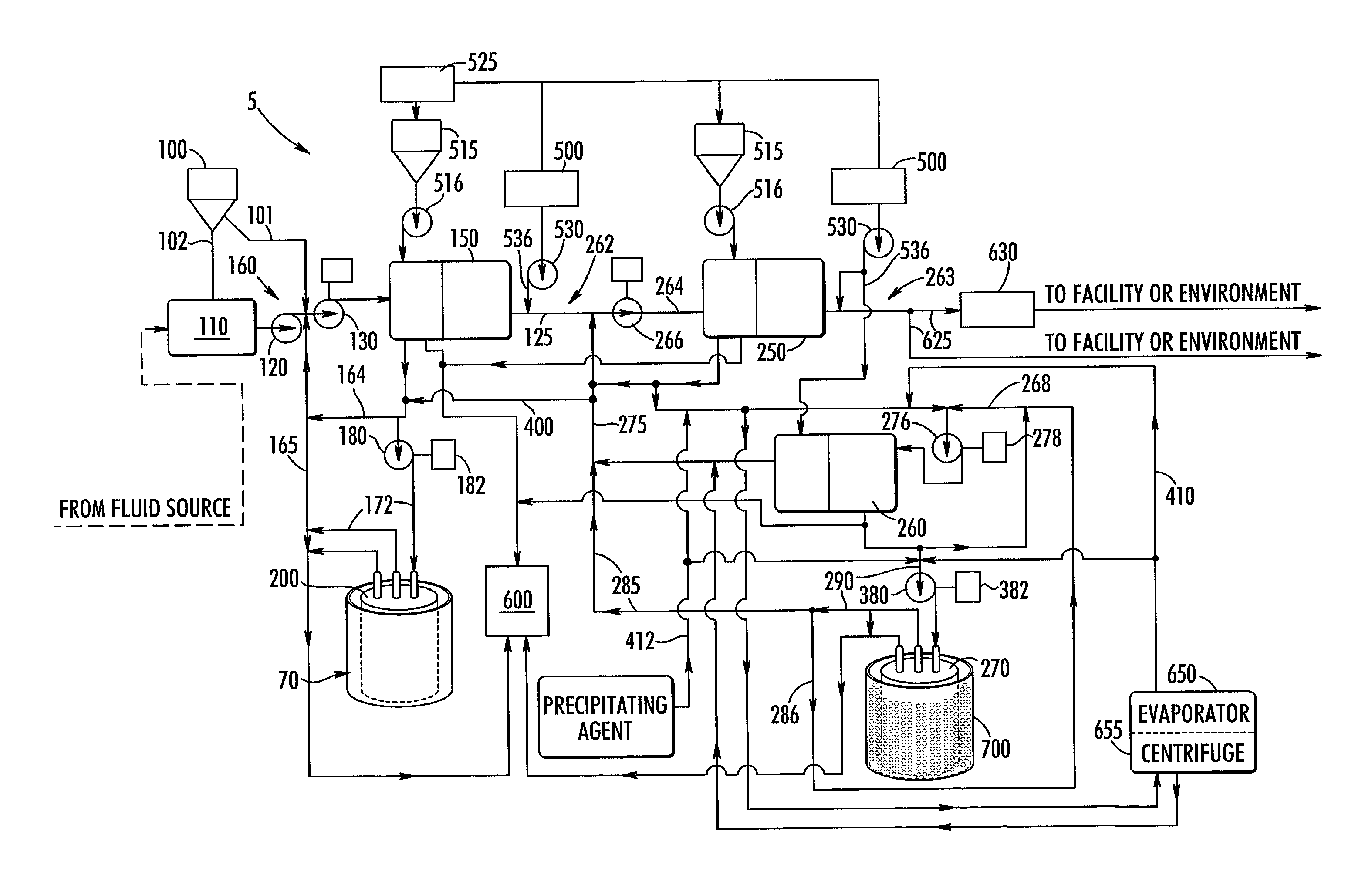
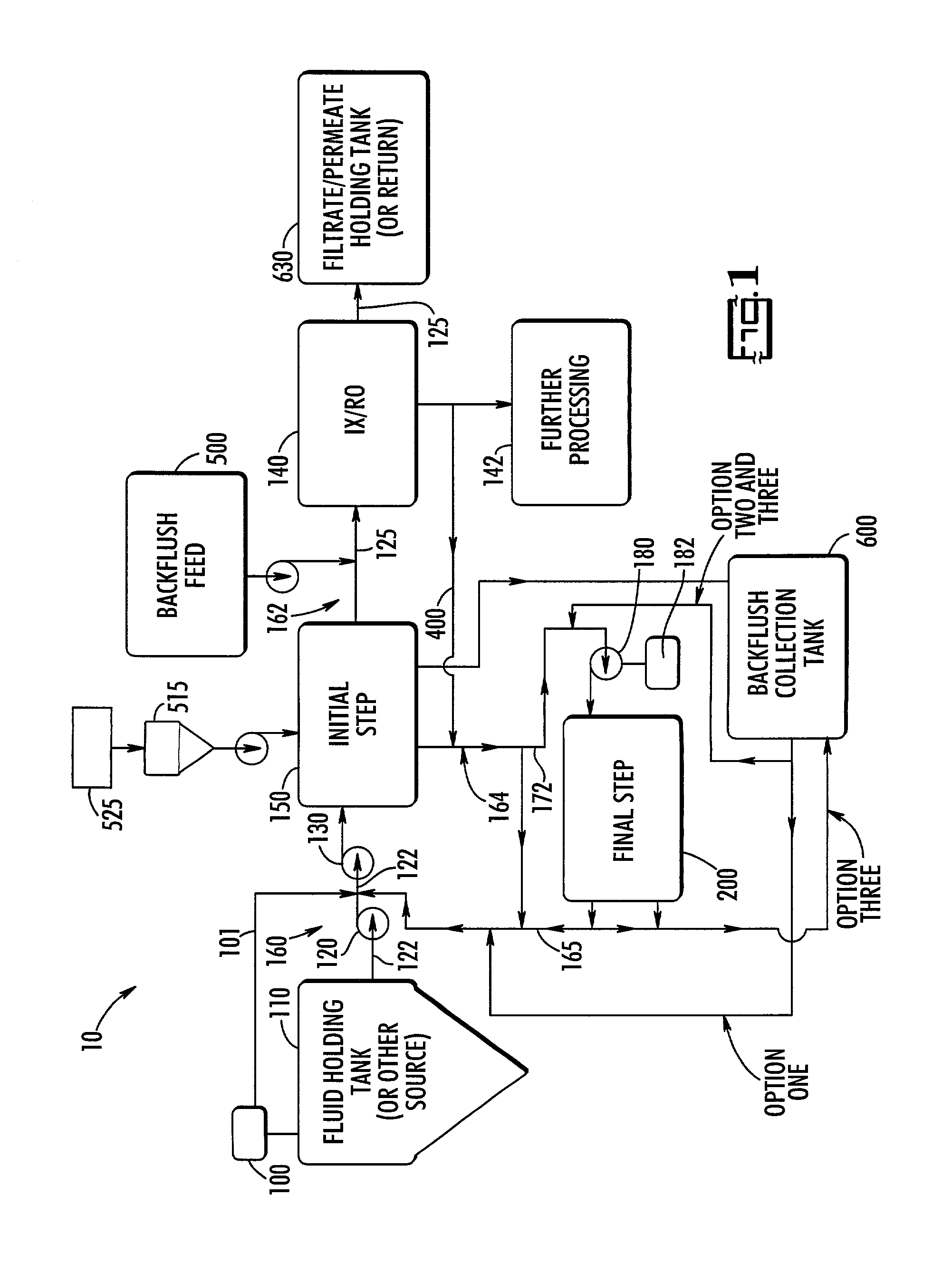
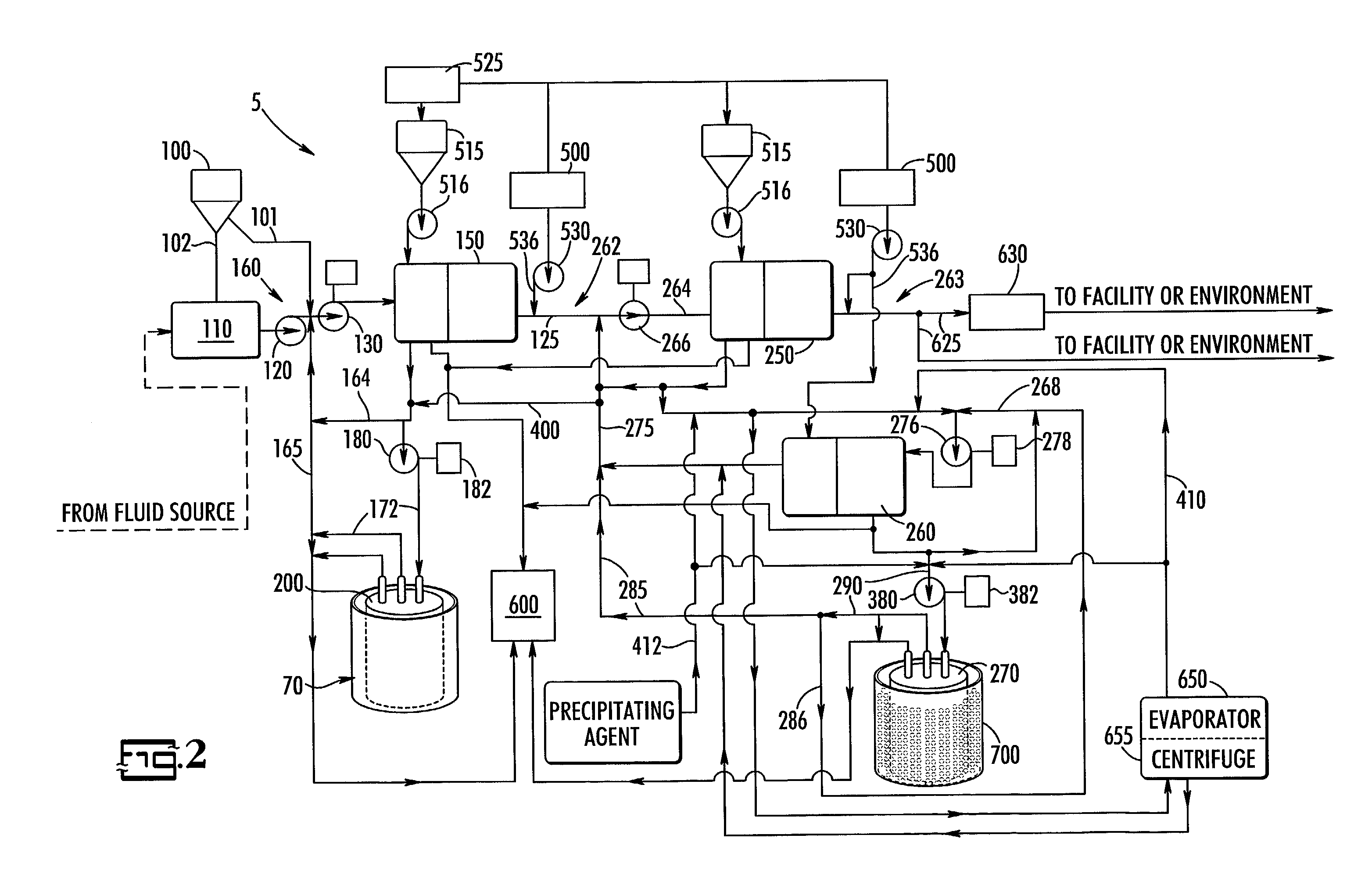
nuclear power plants. To further add to the ease of use, the present invention system includes a multi-purpose container (and / or a modified multi-purpose container) to house and / or process the final step substance collection device and / or its collected substances. The multi-purpose container (and / or its modified version) is a combination processing
enclosure, transport container, and disposal container that allows for the direct processing of the collected substances (including, but not limited to, fluid removal and / or solidification processes) while the final step substance collection device is still attached to the remaining components of the present invention system. This is especially convenient and provides for both material and labor
cost savings by eliminating intermediate handling and processing steps extant in other prior art systems.
[0025]Besides having reject recirculation streams and / or recycle loops, the
usable surface area of some of the filter elements is maximized and the
chemical cleaning requirements of these elements are minimized by the additional feature of backflushing. Generally, backflushing is used with the filtering elements of the initial step and / or intermediate step substance collection devices to remove materials deposited on their upstream surfaces. However, backflushing also may be one of the methods used to recover the valuable, desirable, and / or useful materials collected by the final step substance collection device(s), and after backflushing the final step substance collection device may be available for reuse in the present system. For example,
carbon dioxide, other gases, and / or volatile fluids can be used to backflush the collected materials from the
filter element(s) in order to recover and / or reuse such substances. Furthermore, the efficiency of backflushing, as used in the present system, can be improved by using a pump or by pressurizing the backflushing fluid to produce a
high velocity reverse flow through the filter elements of the substance collection device being backflushed. Efficiency also can be improved by introducing air or
ozone, or any other suitable gas, preferably under pressure, into the backflush fluid and / or into the reject recirculation
stream carried by the recycle loop, and / or by using
ultrasonic technology to dislodge substances from the filter elements. And, since the reject recirculation
stream flows across the upstream surface(s) of the initial step substance collection device at a
high velocity, it would improve backflushing effectiveness by increasing turbulent flow, which would cause the laminar flow layer across the surface of the
filtration elements to decrease allowing more cleaning to occur, which, should increase the
usable lifetime of the substance collection device being backflushed. Additionally, the effectiveness of backflushing and / or the cleaning of the initial step and / or intermediate substance collection device surfaces may be improved by introducing chemical and / or bacterial cleaning agents into the backflushing fluid, and / or chemical, and / or bacterial, and / or mechanical cleaning agents into the reject recirculation
stream. This should allow a more effective cleaning of the particulate from the laminar flow areas of the backflushed collection devices to occur. In some applications, instead of directly processing the materials released during backflushing, the materials may be collected and stored in a backflush collection tank, and later released back into the system for processing or properly disposed of through other means.
[0026]The present invention is being described with frequent reference to radioactive contaminants generated at
nuclear power plants. However, it is applicable to all fluid media having suspended particulate, dissolved materials, and / or any other appropriate species suitable for collection from such media. For example, but not as a limitation, the present invention can be used for the
recovery of valuable and / or useful substances associated with
metal finishing,
metal recovery, and / or
ceramic production.
[0027]Also included among its many uses, the present invention system provides the
advantage of being an alternative to fluid
bed processing and its associated risks, and it can be used to stabilize, e.g., solidify or vitrify,
nuclear reactor and other hazardous wastes prior to disposal, preferably, as a part of post-collection processing.
[0028]Still another
advantage of the present system is that it has “low-shock” characteristics including, but not limited to, the absence of thermal processing, which minimizes the introduction of changes to the molecular structure of proteins and nucleic acids, so that their original biological properties are not degraded. This makes the present invention especially useful for the collection and / or concentration of biotechnical materials or bio-compounds including, but not limited to, pyrogens, proteins, peptides, enzymes, viruses, antigens, and / or bacterial cells. The present invention's characteristics also make it suitable for the synthesization or manufacture of pharmaceutical compounds, and for many other suitable uses including, but not limited to, the collection of macromolecules.
[0029]Another important feature of the present invention is the use of sequential substance collection devices and flow paths, and the preferable use of a final step substance collection device having a particle collection size rating that is equal to or larger than the particle collection size rating of the initial step substance collection device. This feature is counter-intuitive because, in the prior art, fluid media are typically passed through a series of filters, for example, beginning with coarser filters having a
large particle collection size rating and proceeding through finer filters having smaller and smaller particle collection size ratings. However, it should be noted that while this is the preferred particle collection size configuration, there may be uses of the present system in which it would be desirable to have a final step and / or an intermediate step substance collection device with a particle collection size rating that is smaller than the collection size rating of any of the preceding substance collection device in the sequence of collection devices.

