Memory module with dynamic termination using bus switches timed by memory clock and chip select

a memory module and bus switch technology, applied in the field of memory modules, can solve the problems of serious power drain from the termination voltage source, large capacitance of the inputs to the memory modules, and significant dram input capacitan

Inactive Publication Date: 2006-06-27
DIODES INC
View PDF11 Cites 45 Cited by
  • Summary
  • Abstract
  • Description
  • Claims
  • Application Information

AI Technical Summary

Problems solved by technology

These DRAM-input capacitances can be significant, producing a large capacitive load on the inputs to the memory modules, especially when many DRAM chips are mounted on the same memory module.
This can be a serious power drain from the termination voltage source, and a significant amount of heat can be generated by resistor 18 and other termination resistors that must be dissipated by a heat sink attached to the memory module.
Some memory modules have large cumbersome heat sinks attached to dissipate the heat generated in part from such large termination currents.
While useful, the transition detector may be triggered by noise on the line, and may not be on for the very start of a transition.

Method used


Image

  • Memory module with dynamic termination using bus switches timed by memory clock and chip select
  • Memory module with dynamic termination using bus switches timed by memory clock and chip select
  • Memory module with dynamic termination using bus switches timed by memory clock and chip select

Examples


Embodiment Construction

[0026]The present invention relates to an improvement in memory module terminators. The following description is presented to enable one of ordinary skill in the art to make and use the invention as provided in the context of a particular application and its requirements. Various modifications to the preferred embodiment will be apparent to those with skill in the art, and the general principles defined herein may be applied to other embodiments. Therefore, the present invention is not intended to be limited to the particular embodiments shown and described, but is to be accorded the widest scope consistent with the principles and novel features herein disclosed.

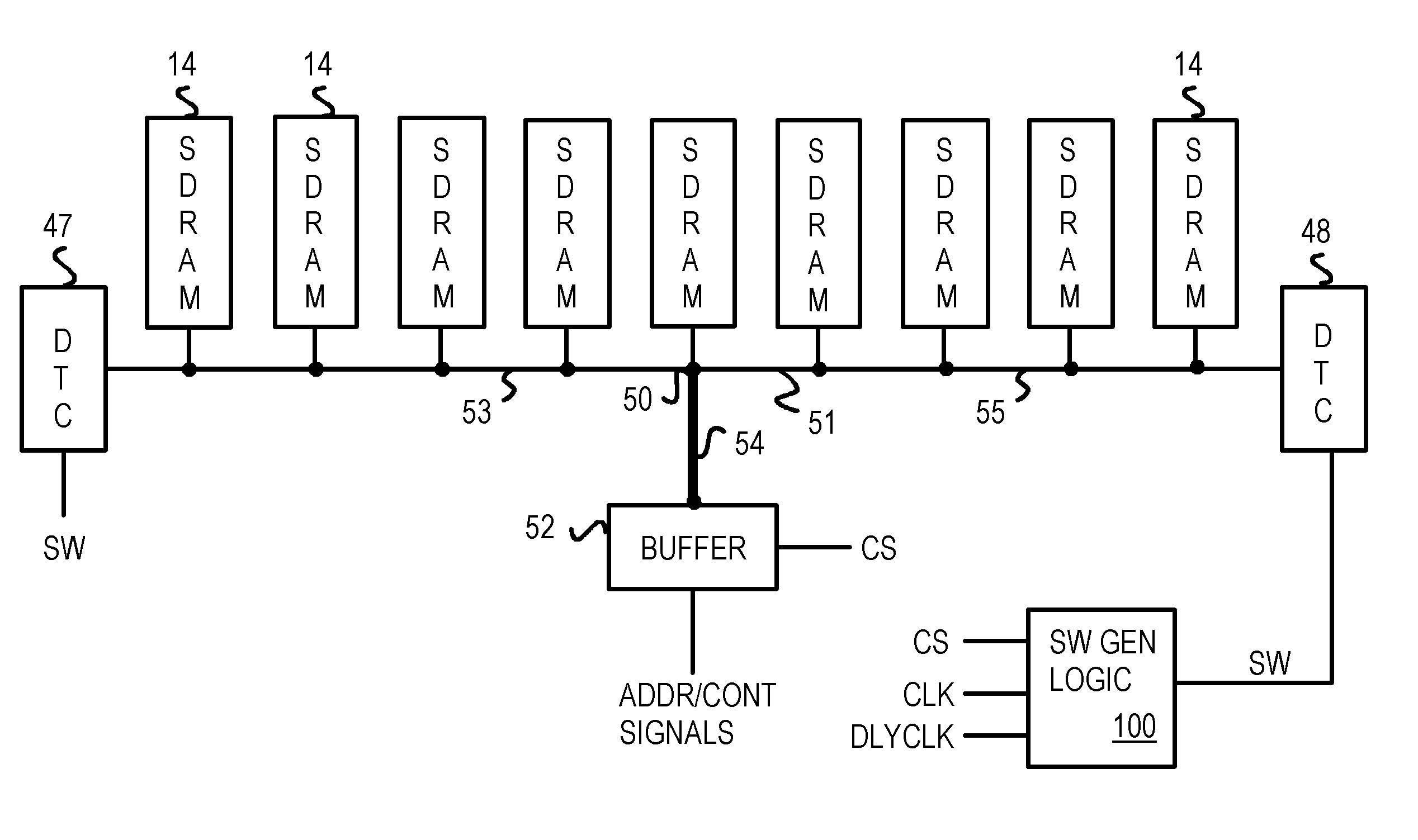
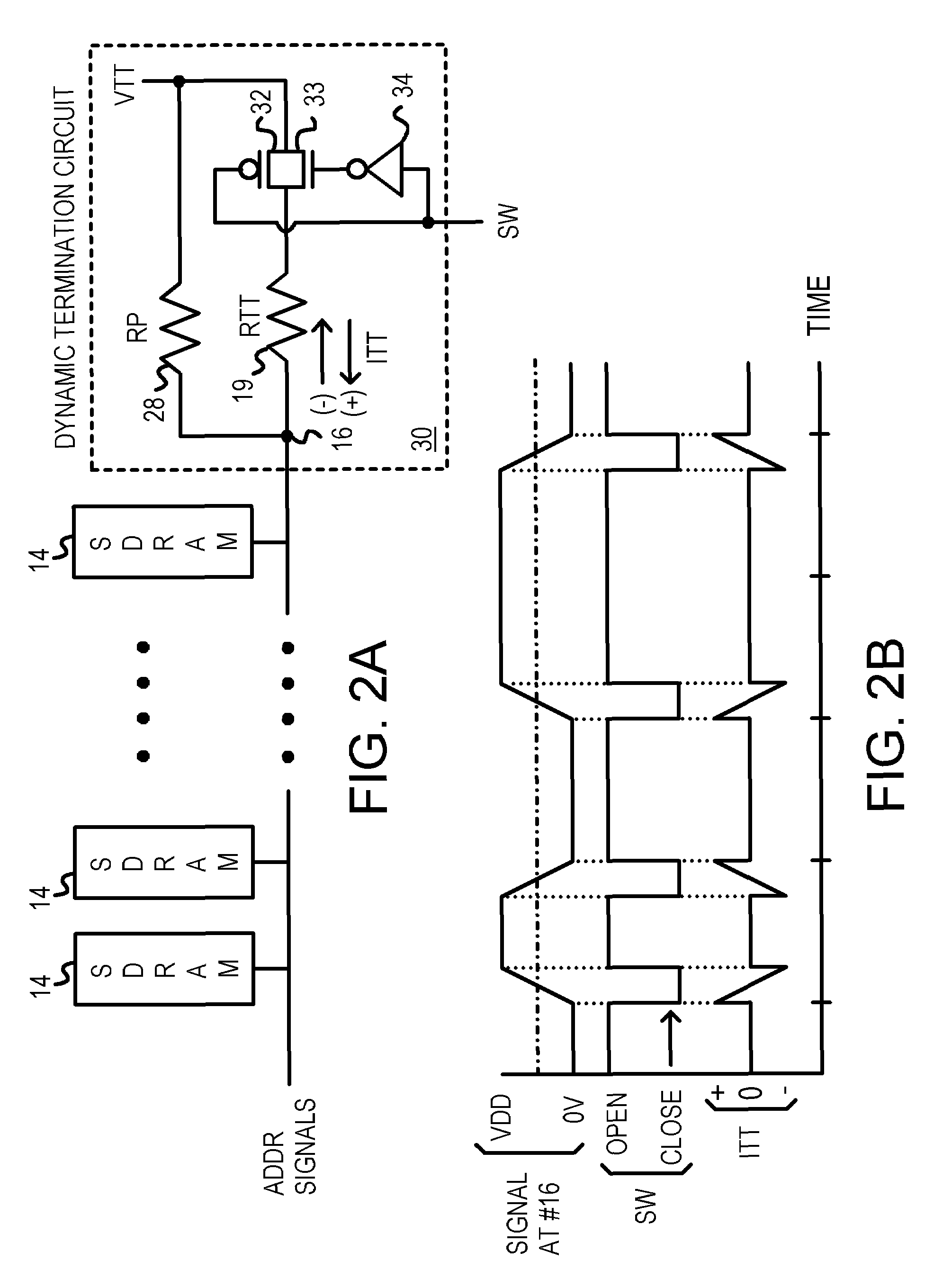
[0027]The inventor has realized that the synchronous nature of SDRAMs may be used to generate timing for activating an active termination circuit for a memory module. The dynamic termination is enabled only when chips on the memory module are selected by the chip-select signal. Also, even when enabled by chip-select, the dyn...


PUM


Abstract

A low-power memory module has an active termination circuit at each end of critical signal traces. The dynamic termination circuit has a low-value resistor that is connected to a termination voltage by a transmission gate that is turned on by a switch signal. The switch signal is activated when the memory module is selected by a chip-select signal, and when a time window is open. The time window is generated from the clock to synchronous DRAMs on the memory module. The time window can be one-quarter of the clock period by ANDing the clock and a delayed clock that is delayed by one-quarter of a cycle. A static terminating resistor in parallel with the low-value resistor provides a much smaller terminating current that is not switched on and off. Traces can be impedance-matched at junctions to branches that each has a dynamic termination circuit at the far end.

Description

CROSS REFERENCE TO RELATED APPLICATIONS[0001]This application is a continuation-in-part of the application for “Trace-Impedance Matching at Junctions of Multi-Load Signal Traces to Eliminate Termination”, U.S. Ser. No. 10 / 707,249, filed Dec. 1, 2003 is now a U.S. Pat. No. 6,927,992, which is a continuation-in-part of the application for “DDR Memory Modules With Input Buffers Driving Split Traces with Trace-Impedance Matching at Trace Junctions”, U.S. Ser. No. 10 / 249,845, filed May 12, 2003 is now a U.S. Pat. No. 6,947,304.BACKGROUND OF INVENTION[0002]This invention relates to memory modules, and more particularly to dynamic, timed termination circuits.[0003]Personal computers (PCs) and other electronic systems often use memory modules such as dual-inline memory modules (DIMMs). Memory modules have memory chips such as dynamic-random-access memories (DRAMs) mounted on a small printed-circuit board (PCB) or other substrate. Contact pads along one edge of the substrate make electrical ...

Claims


Application Information

Patent Timeline
Patent Type & Authority Patents(United States)
IPC IPC(8): H03K19/003G11C5/06H03K17/16G11C5/00H03K17/00H03K19/00
CPCG06F13/4086G11C5/04Y02B60/1235Y02B60/1228H04L25/0298Y02D10/00
Inventor YEN, YAO TUNG
Owner DIODES INC
Why Eureka
Try Eureka