Spindle motor for hard disk drives

Active Publication Date: 2006-06-27
MINEBEAMITSUMI INC
View PDF15 Cites 3 Cited by
  • Summary
  • Abstract
  • Description
  • Claims
  • Application Information

AI Technical Summary

Benefits of technology

[0008]Nevertheless, a very favorable retention effect and a firm press fit of the shaft in the base plate can be achieved, since a larger surplus can be used in the remaining joint segments.
[0009]Consequently, the shaft can be connected to the base plate in a manner that is less damaging to the components.
[0010]In a preferred embodiment of the invention, the outer diameter of the shaft in proximity to the notch is substantially smaller than the inner diameter of the drilled hole in the base plate. Consequently, the shaft does not contact the inside wall of the drilled hole in the base plate in the area surrounding the notch, and no adhesive forces are created in this area. This facilitates the insertion of the shaft.
[0011]The notch preferably continues

Problems solved by technology

An excessive surplus would lead to an unacceptable strain on the components.
If the surplus or the joint length is reduced, adhesive str

Method used


Image

  • Spindle motor for hard disk drives
  • Spindle motor for hard disk drives
  • Spindle motor for hard disk drives

Examples


Embodiment Construction

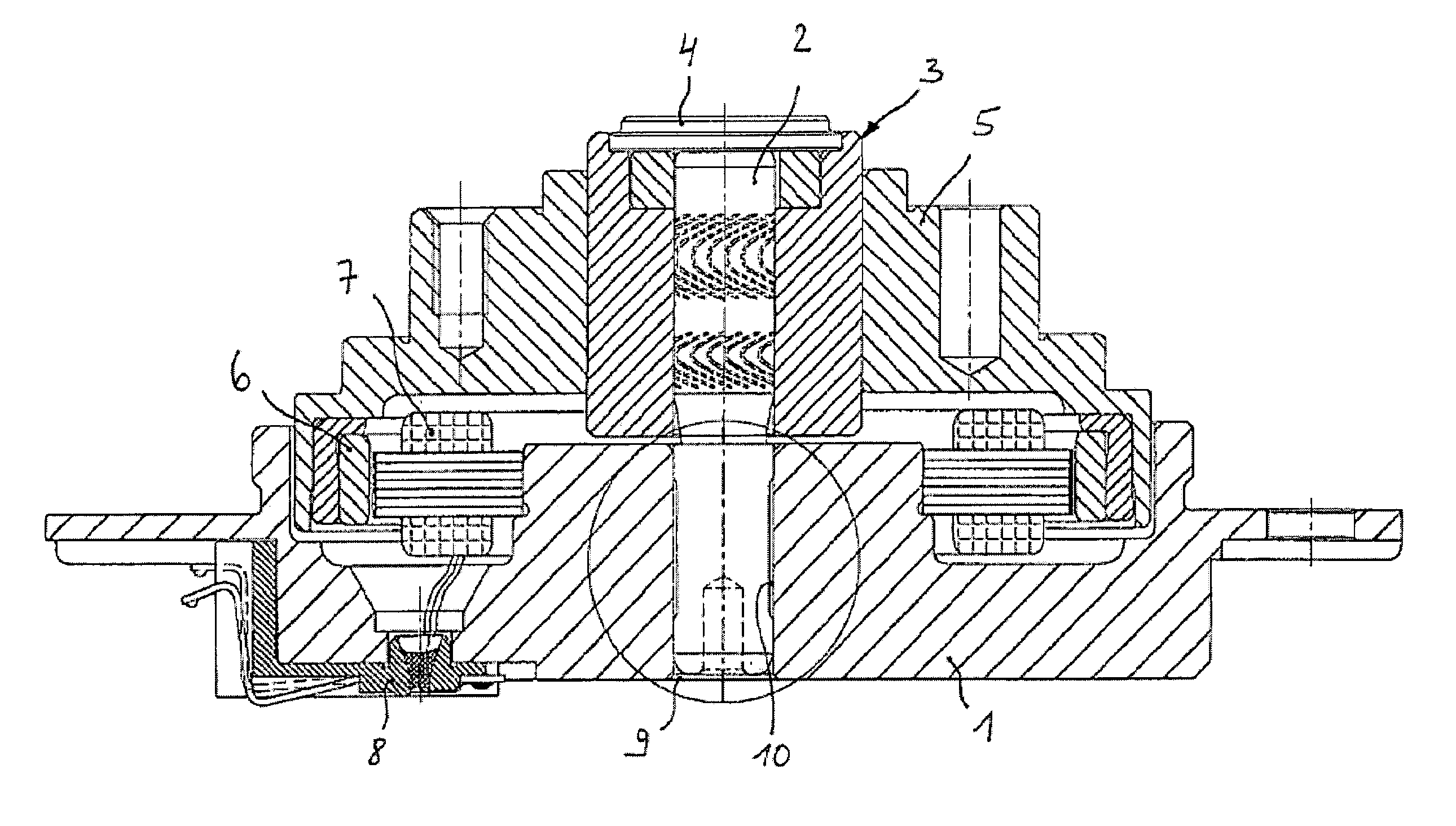
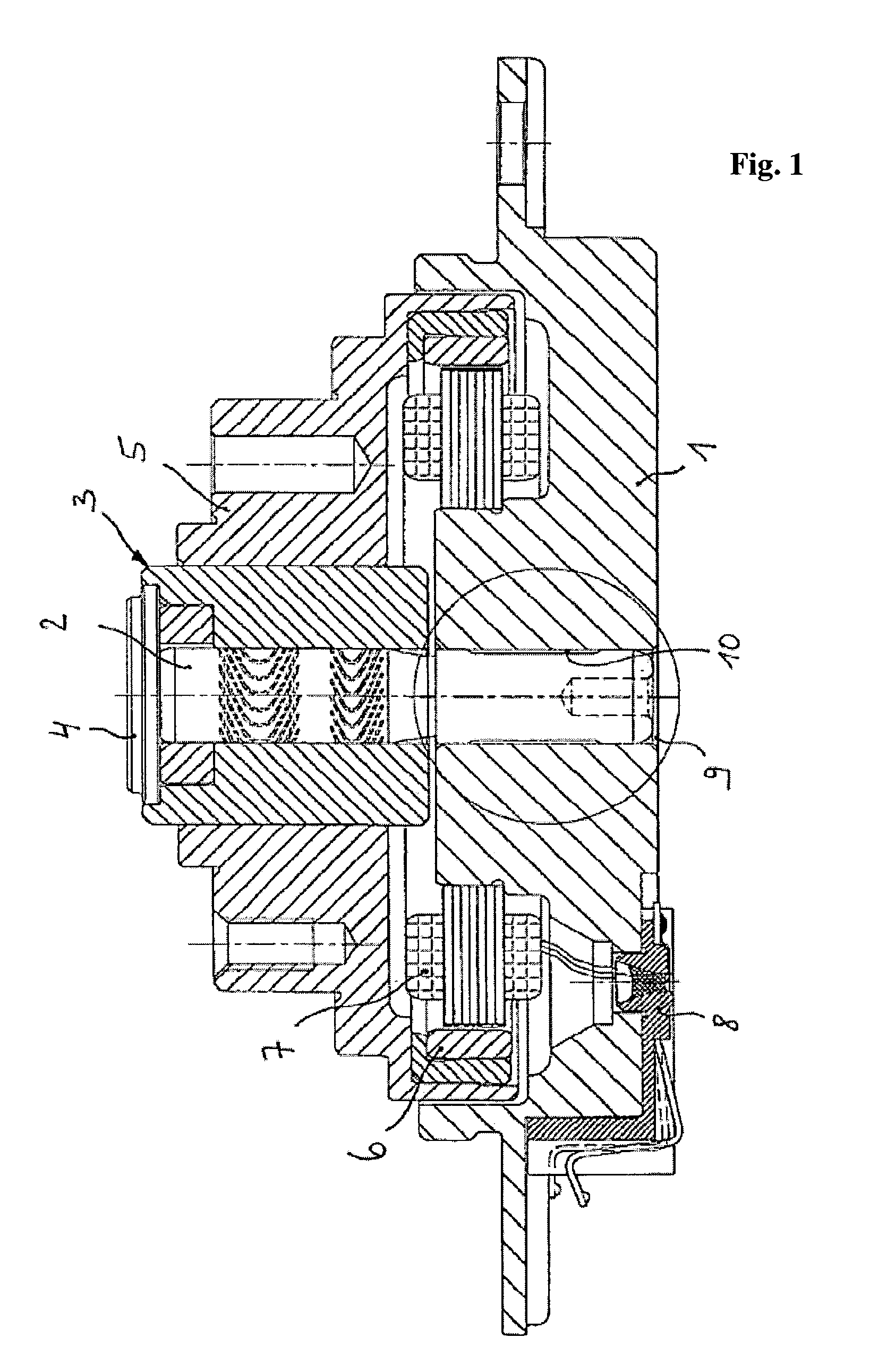
[0020]As shown in FIG. 1, in accordance with the preferred embodiment of the present invention, a spindle motor is provided having a base plate 1 and a shaft 2 firmly connected to the base plate. A rotor 5 is rotationally mounted on shaft 2 by means of a bearing system 3, preferably structured as a hydrodynamic sliding bearing system. Bearing system 3 is protected from the exterior by a lid 4. Rotor 5 is equipped with rotor magnets 6 located along rotor's inner circumference. Rotor magnets correspond to a plurality of electrical coils located on a fixed stator 7 arranged on the base plate 1. Rotor 5 is actuated by an alternating electric field generated by the electrical coils interacting with the rotor magnets. A contacting unit 8 is provided to supply an electrical current to the electrical coils of stator 7.

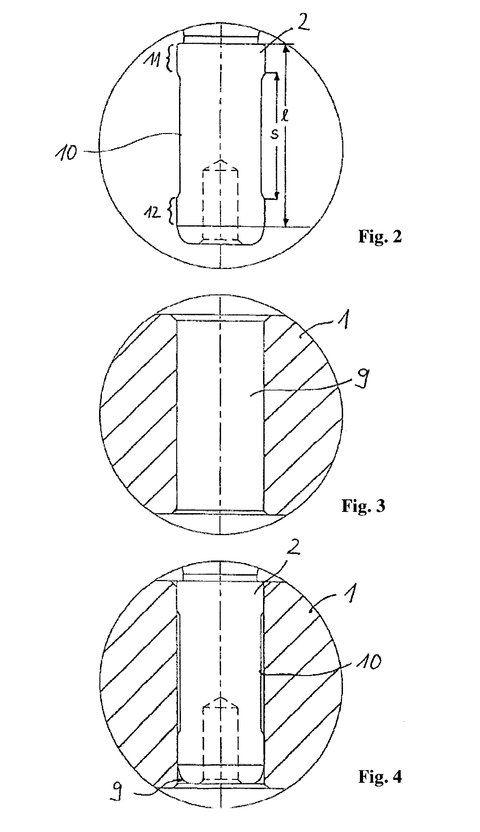
[0021]As shown in FIG. 3, base plate 1 features a cylindrical drilled hole 9 with a predetermined constant inner diameter. One end of shaft 2 is accepted in a forced fit into ...


PUM


Abstract

A spindle motor for use in hard disk drives having a base plate, a stationary shaft, a rotationally driven rotor, and a bearing system rotationally supporting the rotationally driven rotor. The shaft is fixedly mounted on the base plate. The base plate includes a drilled hole for insertion of a portion of the shaft such that this shaft's portion and the inner surface of the hole define a joint length l, when this portion is pressed into the drilled hole. The shaft has at least one notch located along the shaft's circumference and interrupting the joint length l.

Description

CROSS-REFERENCE TO RELATED APPLICATIONS[0001]This application claims all rights of priority to German Patent Application Ser. No. 201 19 716.2, filed Dec. 5, 2001 (pending).BACKGROUND[0002]The invention relates to a spindle motor for memory devices such as hard disk drives.[0003]Conventional spindle motors for hard disk drives include a base plate or a base flange, a shaft, and a bearing system for rotationally supporting a motor's rotor driven by an electromagnetic force. The bearing system may be structured as a rolling bearing system or a hydrodynamic sliding bearing system.[0004]In a conventional spindle motor having a stationary shaft, the shaft is firmly connected to the base plate or the base flange by means of a press-fit connection. To accomplish the connection, the base plate or the base flange features a drilled hole of a predetermined diameter and a predetermined length. One end of the shaft is pressed into and secured within the drilled hole. The outside diameter of the...

Claims


Application Information

Patent Timeline
IPC IPC(8): G11B17/02H02K5/167F16C35/02H02K5/16H02K7/00H02K7/08
CPCF16C35/02H02K7/003H02K5/165F16C17/107F16C2370/12
Inventor KULL, ANDREAS
Owner MINEBEAMITSUMI INC
Why Eureka
Try Eureka