Method and apparatus for accurate fan tachometer readings of PWM fans with different speeds

a technology of pwm fans and tachometers, which is applied in the direction of ignition automatic control, instruments, electric controllers, etc., can solve the problems of low accuracy, inability to accurately measure the speed of a fan, and the tachometer signal output of the fan may not represent the current fan speed during the time between pulses, so as to achieve accurate measurement of the speed of the fan, maintain smooth fan operation, and minimize audio noise and sensitivity to electrical noise.

Inactive Publication Date: 2006-06-27
MICROCHIP TECH INC
View PDF37 Cites 10 Cited by
  • Summary
  • Abstract
  • Description
  • Claims
  • Application Information

AI Technical Summary

Benefits of technology

[0014]Thus, various embodiments of the systems and methods described above may facilitate design of a system that uses a test or sampling signal to accurately measure the speed of a fan in an electrical system while minimizing audio noise and sensitivity to electrical noise, and maintaining smooth fan operation, where only a maximum frequency for the test or sampling signal specific to the fan needs to be programmed for each fan.

Problems solved by technology

One issue associated with employing PWM signal generators to power fan circuits that typically incorporate three-wire fans is that the tachometer circuitry associated with the fans does not receive power during the time the fans themselves are not powered, that is, between the PWM pulses.
In general, this issue may pose a problem whenever the method to power the fan circuits involves use of a non-continuous power supply, that is, when power is not continuously provided to the fan, e.g., a PWM signal generator.
As a result, the tachometer signal output by the fan may not represent the current fan speed during the time between pulses.
There are, however, disadvantages associated with such techniques, including low accuracy, especially at low PWM duty cycles, fan speed surges resulting directly from stretching the PWM pulse and unwanted fan noise resulting from the fan speed surges.
Another drawback is that the stretching typically dominates at low PWM duty cycles.
Such techniques generally lead to complicated implementations with significant impact on die size, and are typically prone to electrical noise sensitivity.

Method used


Image

  • Method and apparatus for accurate fan tachometer readings of PWM fans with different speeds
  • Method and apparatus for accurate fan tachometer readings of PWM fans with different speeds
  • Method and apparatus for accurate fan tachometer readings of PWM fans with different speeds

Examples


Embodiment Construction

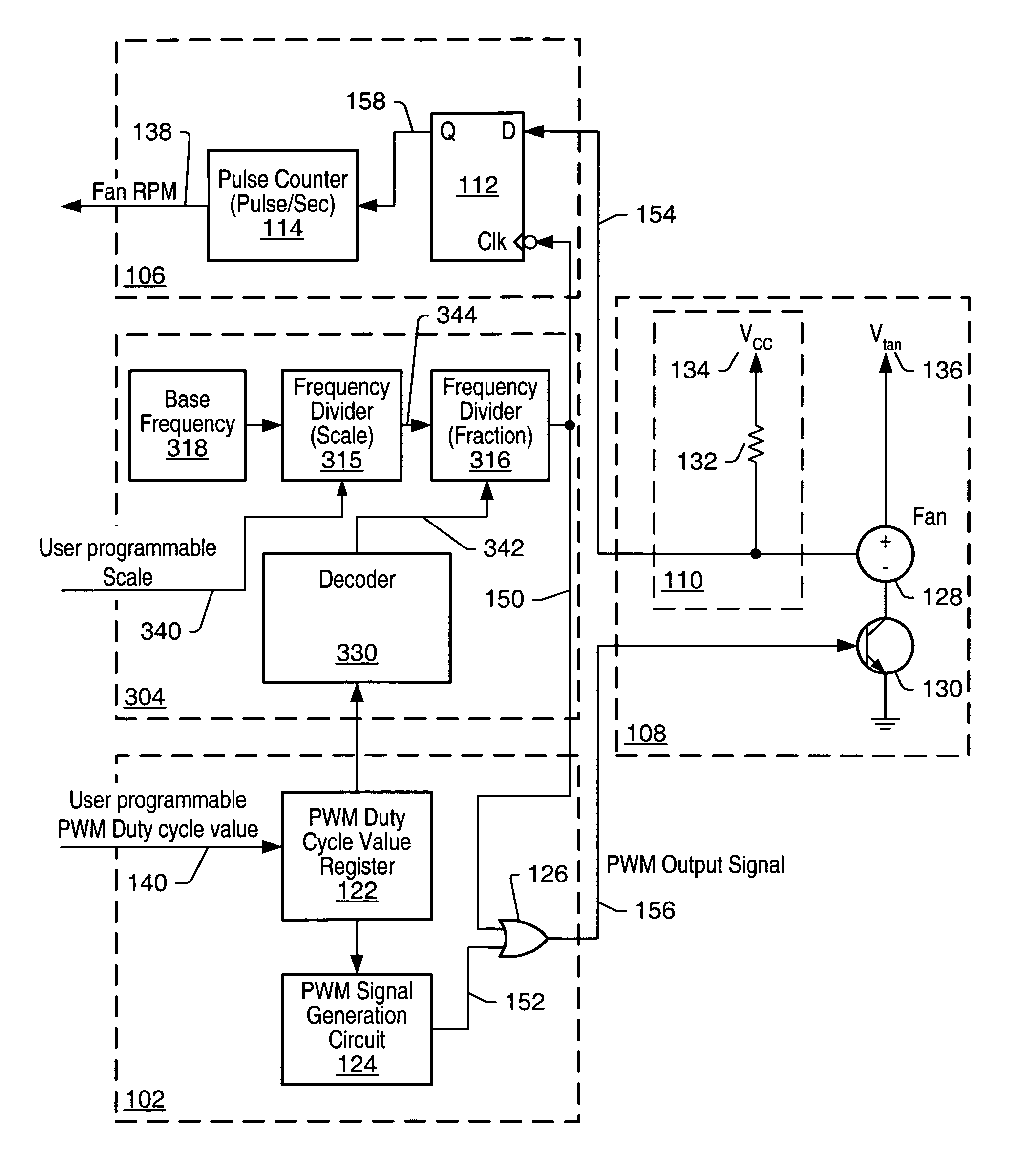
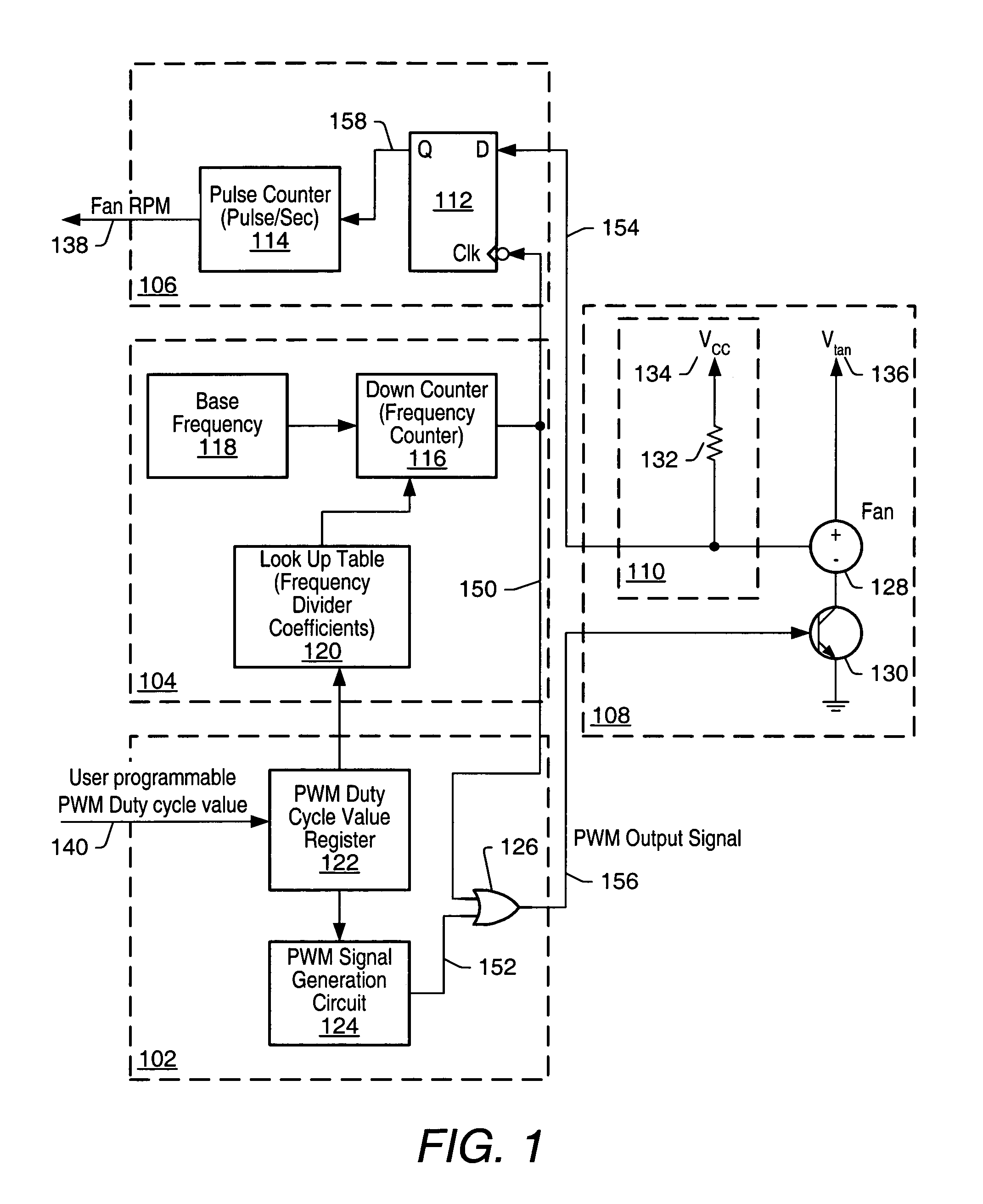
[0022]As used herein, a “trigger” signal is defined as a signal that is used to initiate, or “trigger”, an event or a sequence of events in a digital system. A trigger signal is said to be in a “triggering state” at a time when it initiates a desired event, or sequence of events. A periodic trigger signal may commonly be referred to as a “clock”. In a “synchronous” digital system, generally a clock, commonly referred to as a “system clock”, may be used for initiating most events, or sequences of events. An example of a triggering state may be, but is not limited to, a rising edge of a pulse of a clock in a synchronous digital system. A “frequency” of pulses refers to a number of pulses that may appear within a selected unit period of time. For example, if twenty pulses appear within duration of one second, then the frequency of the pulses is 20 Hz.

[0023]When an event, or a sequence of events, is said to be initiated “in response to” receiving a stimulus signal, it may be implied tha...


PUM


Abstract

A system and method for generating a test signal used in measuring the speed of a rotating device, such as a fan in a computer system is disclosed. A pulse width modulated (PWM) signal may power the fan with the duty cycle of the PWM signal controlling the speed of the fan. The fan may generate tachometer pulses used for monitoring RPM of the fan. The frequency of the test signal may be selected to be at least twice the frequency of the tachometer pulses. The test signal may be generated from a base frequency signal using two cascaded frequency dividers. The first divider may output a scaled base frequency signal obtained by dividing the base frequency signal by a user programmable scale frequency coefficient corresponding to a maximum test signal frequency for the fan. The second divider may output the test signal by dividing the scaled base frequency signal by a fraction frequency coefficient obtained from and proportional to the current PWM duty cycle value. The test signal may be multiplexed with the PWM signal to obtain existing tachometer pulses even when the PWM signal is not asserted. The scale frequency coefficient may only need to be programmed once for each fan.

Description

BACKGROUND OF THE INVENTION[0001]1. Field of the Invention[0002]This invention relates to cooling equipment for electronic systems, e.g., fans, and more particularly, to measuring the rotational speed of a fan.[0003]2. Description of the Related Art[0004]Fans are often used to evacuate warm air from enclosures in which electronic systems are contained. For example, most computer systems include one or more cooling fans to aid in circulating the air inside the enclosures and for maintaining the temperature inside the enclosures within an acceptable range. The increased airflow provided by fans typically aids in eliminating waste heat that may otherwise build up and adversely affect system operation. Employing cooling fans is especially helpful in ensuring proper operation for certain central processing units (CPUs) with relatively high operating temperatures.[0005]Control of fans in a system typically involves a fan control unit executing a fan control algorithm. A fan control algori...

Claims


Application Information

Patent Timeline
Patent Type & Authority Patents(United States)
IPC IPC(8): G01P3/00H02P7/06G01P3/48G06F15/00
CPCG01P3/48
Inventor BEKKER, LEONID A.SEGAL, URI
Owner MICROCHIP TECH INC
Why Eureka
Try Eureka