
System for addressing a data storage unit used in a computer

Inactive Publication Date: 2006-06-27
JEONG MYUNG KI
View PDF20 Cites 4 Cited by
  • Summary
  • Abstract
  • Description
  • Claims
  • Application Information

AI Technical Summary

Benefits of technology

[0007]It is, therefore, a primary objective of the present invention to provide a system, which is capable of dividing a memory into a plurality of equally-sized sub-memories and controlling an address of each sub-memory, thereby significantly increasing the access speed to an auxiliary memory unit.

Problems solved by technology

However, an increased number of clients create a bottleneck between a server and auxiliary memory units.
As a result, access time would be longer and, worst, due to excessive load on the network, the network could be down or transmitted data could be lost.
In a server system such as game servers where tens of thousands of clients could simultaneously connect at one time, read and write requests from individual clients in the server can impose a serious load to the system.
Servers with the HDD having a finite access time would not be able to handle ever increasing and faster data traffic.
It could adversely affect the stabilization of the servers.
CPUs used in typical servers can address only up to several Giga-byte memory map ranges so that they cannot directly control a data storage capacity over tens of Giga-bytes reaching several Tera-bytes.
Furthermore, the CPUs fail directly to drive a plurality of memories due to a fan-out between memory chips.

Method used


Image

  • System for addressing a data storage unit used in a computer
  • System for addressing a data storage unit used in a computer
  • System for addressing a data storage unit used in a computer

Examples


Embodiment Construction

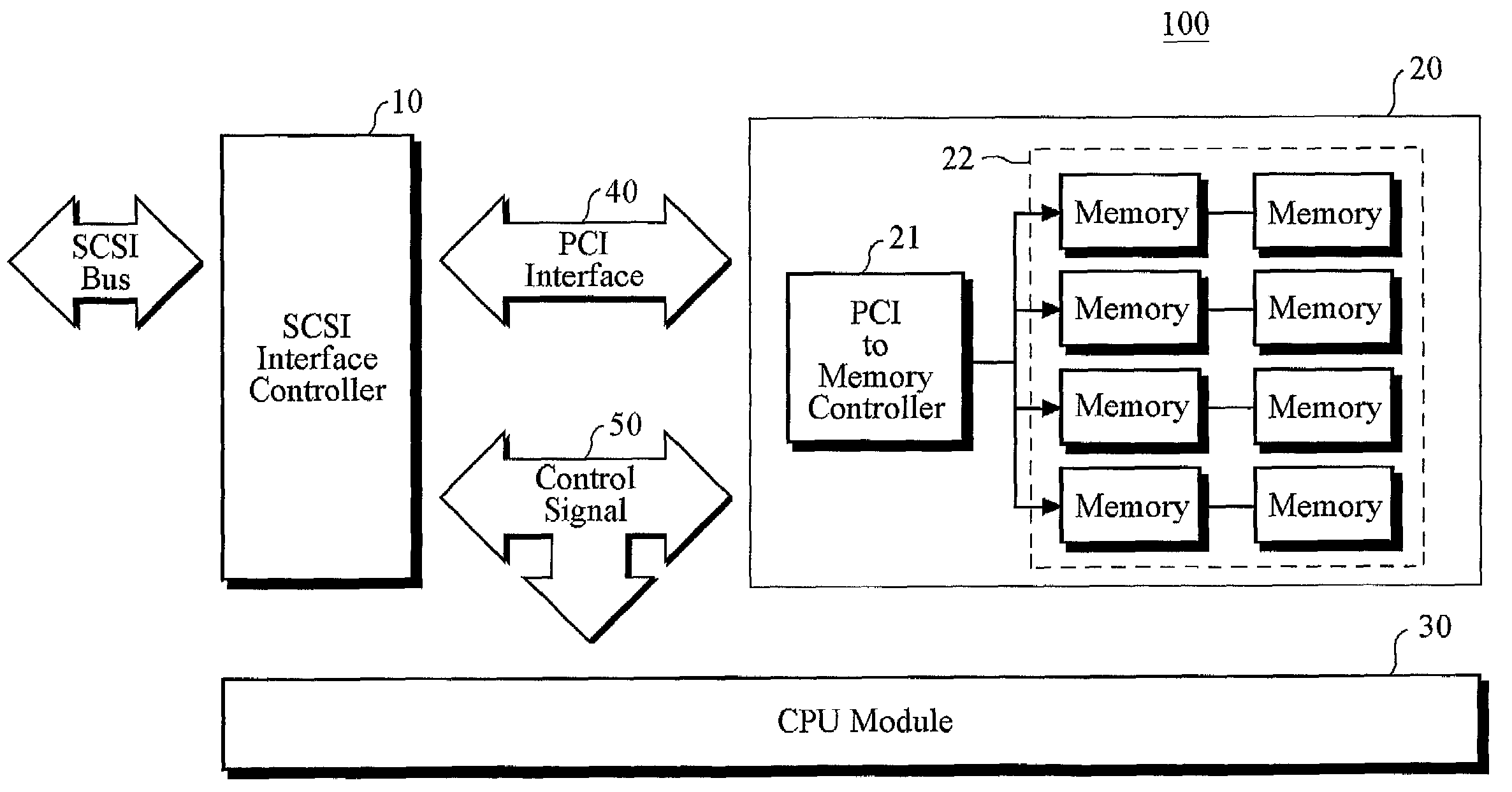
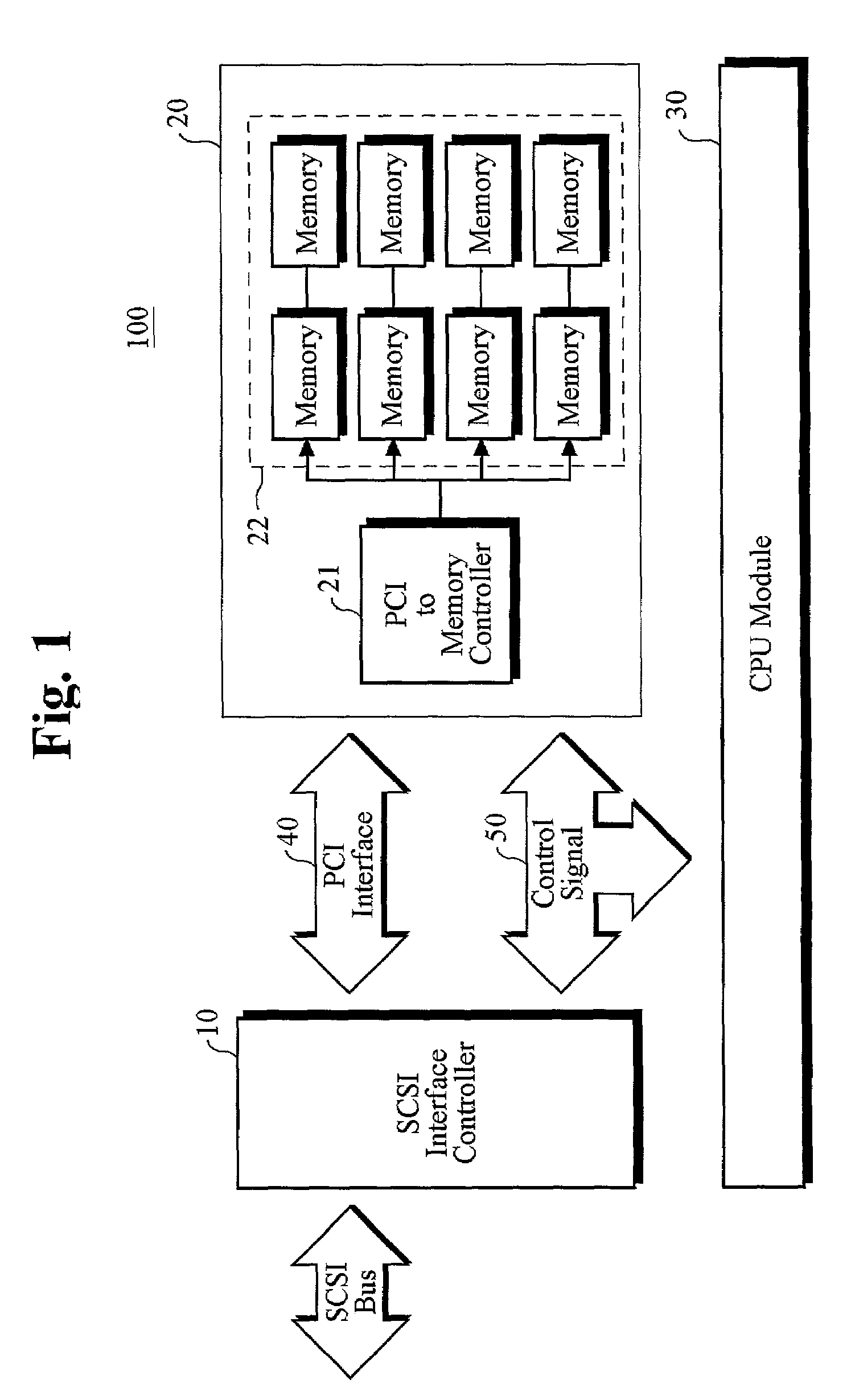
[0014]Referring to FIG. 1, there is shown a schematic diagram of a memory addressing system in accordance with a preferred embodiment of the present invention. The memory addressing system 100 comprises a SCSI interface controller 10, a memory card module 20, a CPU module 30, a PCI interface bus 40, and a control signal bus 50. The SCSI interface controller 10 converts a format of data on an external SCSI (small computer system interface) bus so that the data are accessed on an internal PCI bus adapted to the memory addressing system 100, thereby allowing a SCSI bus command to be processed by the CPU module 30. As is well known, SCSI is one of the industry's standard interfaces that allows personal computers to communicate with peripheral devices, such as disk drives, tape drives, CD-ROM (compact disk-read only memory) drives, printers, and scanners, faster and more flexibly than previous interfaces. SCSI ports are built into most personal computers today and supported by all major ...


PUM


Abstract

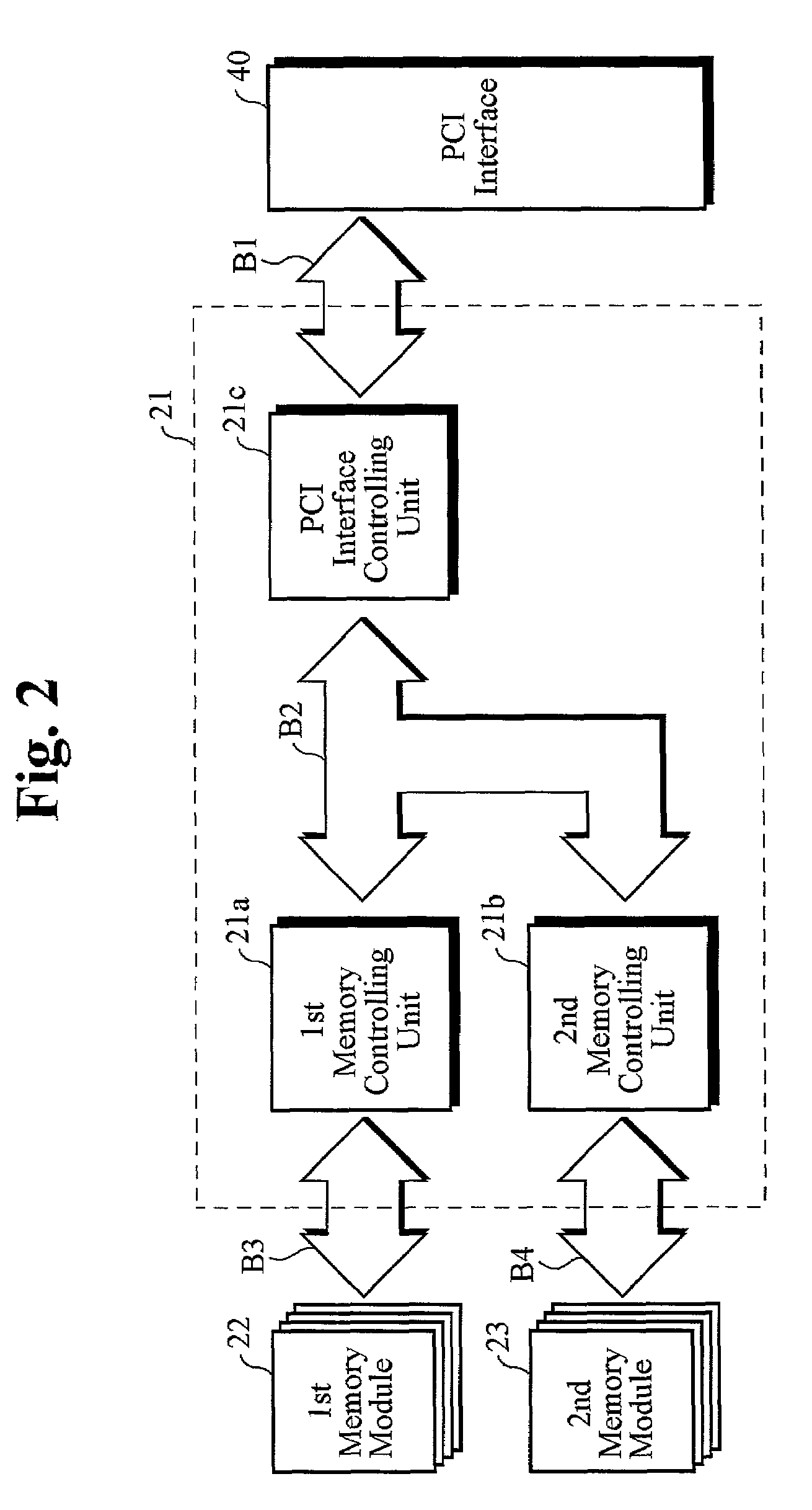
Disclosed is a system, which divides a memory into a plurality of equally-sized sub-memories and controls an address of each sub-memory, thereby significantly increasing the access speed to an auxiliary memory unit, which includes a SCSI (Small Computer System Interface) controller for converting a format of data on a SCSI interface bus so that the data are accessed on a PCI(Peripheral Component Interconnect) interface bus for use in the system, a memory card module for storing data on the PCI interface bus therein, the memory card module being divided into a plurality of equally-sized memory blocks, and a CPU (Central Processing Unit) module for writing data on the PCI interface bus to the memory card module and reading out the data therefrom. The memory card module includes a PCI-to-memory controller, which is disposed between the PCI interface bus and the plurality of sub-memories as a bridge, for controlling access to the plurality of sub-memories, which is distributed in a hierarchical fashion.

Description

FIELD OF THE INVENTION[0001]The present invention relates to an auxiliary storage device and, in particular, to a high-capacity auxiliary memory unit constructed with a memory such as SDRAM (synchronous dynamic random access memory) and a SCSI (small computer system interface) bus structure.BACKGROUND OF THE INVENTION[0002]As personal computers are widely used, a client and server system based on the personal computers now can handle tasks that were once possibly executed by a main frame computer system. Typically, a client and server system includes a high-speed server with a large-capacity auxiliary memory unit and a plurality of personal computers (clients). The server and personal computers are connected via a network, thereby allowing the clients to access the server. Specifically, each client has the ability to write and read information to and from the server and to exchange information with other clients connected to the network.[0003]However, an increased number of clients ...

Claims


Application Information

Patent Timeline
IPC IPC(8): G06F13/00G06F3/06G06F12/06
CPCG06F3/0613G06F12/0623G06F3/0683G06F3/0658G06F3/064G06F13/00
Inventor KIM, SEONG YONG
Owner JEONG MYUNG KI
Learn More