Array-type capacitive pressure pulse wave sensor, and pulse wave measuring apparatus having the same

a capacitive pressure and pulse wave sensor technology, applied in the direction of electrical/magnetic measuring arrangements, instruments, angiography, etc., can solve the problems of large increase in manufacturing costs, significantly inferior cases, and inferior capacitive type pressure sensors in terms of miniaturization compared, so as to achieve accurate and stable measurement of pressure pulse waves, and manufacture cheaply

Inactive Publication Date: 2006-07-04
OMRON HEALTHCARE CO LTD
View PDF2 Cites 17 Cited by
  • Summary
  • Abstract
  • Description
  • Claims
  • Application Information

AI Technical Summary

Benefits of technology

[0018]An object of the present invention is to provide an array-type capacitive pressure pulse wave sensor that can be manufactured inexpensively and that can measure the pressure pulse wave accurately and stably, and a pulse wave measuring apparatus incorporating the same.
[0020]With this configuration, it is possible to increase the arrangement density of the capacitive elements in the direction approximately orthogonal to the extending direction of the artery. Accordingly, accurate and stable measurement of pressure pulse wave is ensured even when the pressure sensor of capacitive type that can be manufactured inexpensively is used as the pressure pulse wave sensor.
[0022]With this configuration, it is possible to readily produce an array-type capacitive pressure pulse wave sensor having capacitive elements arranged in a staggered manner.
[0024]With this configuration, the array-type capacitive pressure pulse wave sensor having capacitive elements arranged in a staggered manner can readily be produced.
[0026]With this configuration, it is possible to produce inexpensively a pulse wave measuring apparatus capable of measuring the pressure pulse wave accurately and stably.
[0027]According to the present invention, highly accurate measurement of the pressure pulse wave using a pressure sensor of capacitive type that can be produced inexpensively becomes possible.

Problems solved by technology

Such miniaturization of the sensor element, however, inevitably increases the manufacturing cost to a large extent.
However, the capacitive type pressure sensor is inferior in terms of miniaturization compared to the pressure sensor using the strain resistance elements manufactured by the semiconductor process.
This is considerably inferior to the case where the pressure sensor of strain resistance type described above is used as the pressure pulse wave sensor.
If such a capacitive pressure sensor is adapted as it is, there will occur a large error in the measured value, hindering measurement with high accuracy.

Method used


Image

  • Array-type capacitive pressure pulse wave sensor, and pulse wave measuring apparatus having the same
  • Array-type capacitive pressure pulse wave sensor, and pulse wave measuring apparatus having the same
  • Array-type capacitive pressure pulse wave sensor, and pulse wave measuring apparatus having the same

Examples


first embodiment

[0058

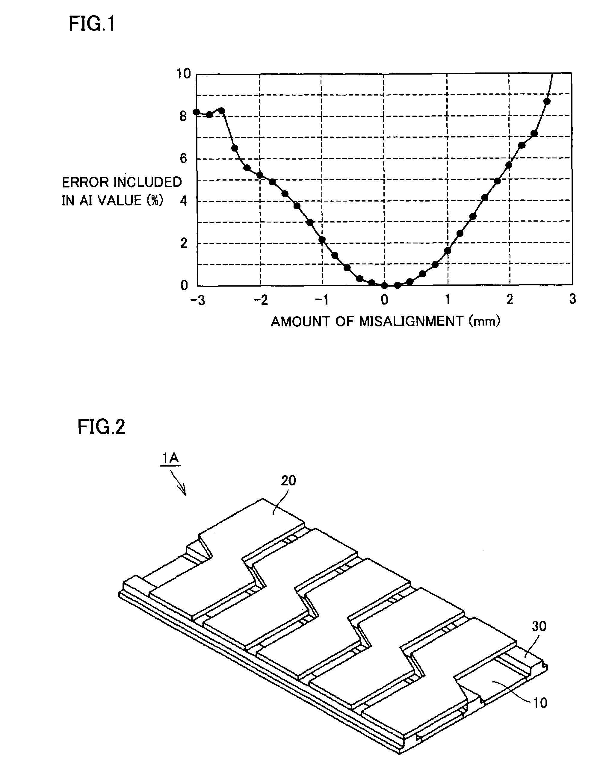
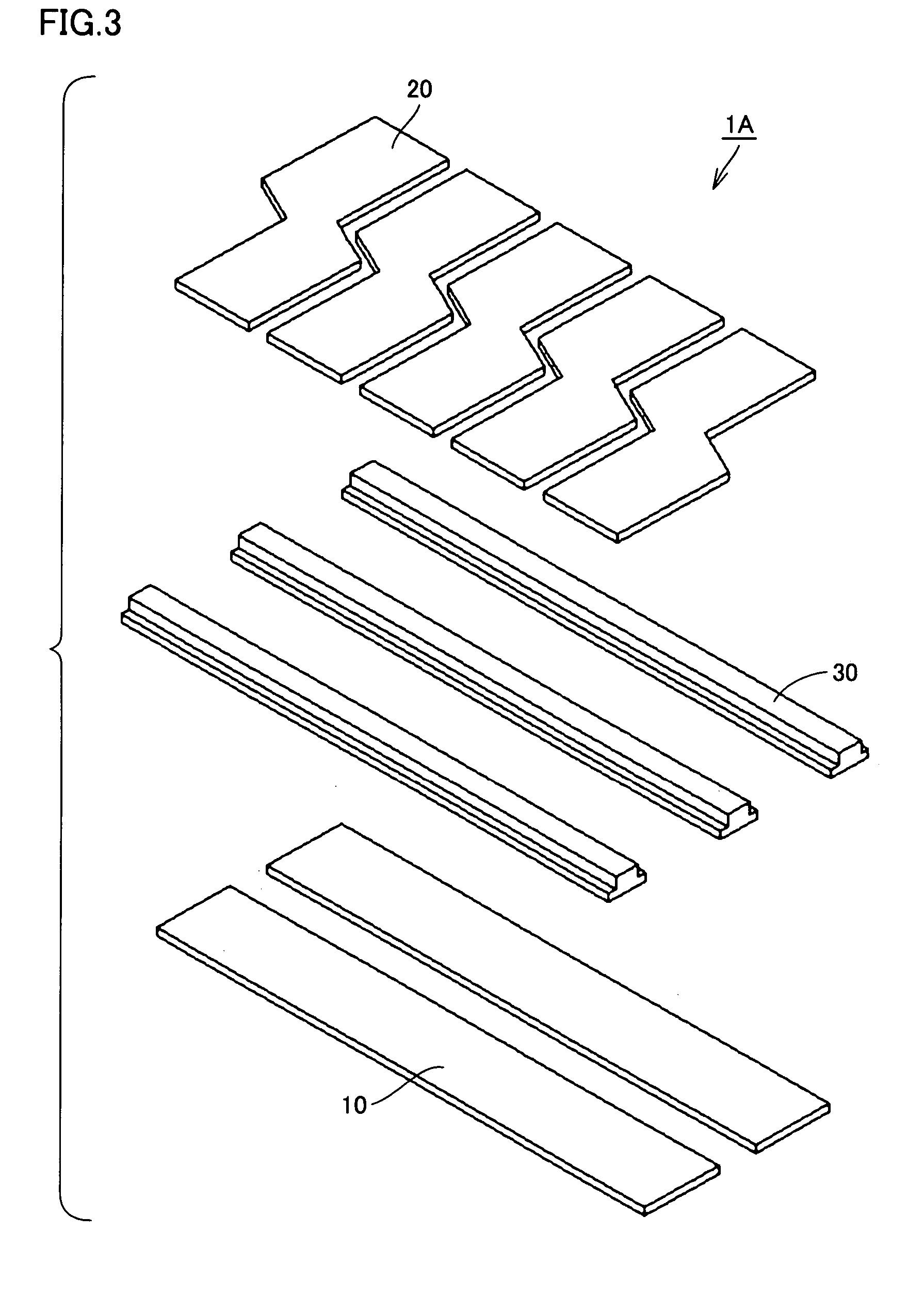
[0059]FIG. 2 is a perspective view of a pressure detecting portion of an array-type capacitive pressure pulse wave sensor according to the first embodiment of the present invention, and FIG. 3 is an exploded perspective view of the pressure detecting portion shown in FIG. 2. FIG. 4A is a plan view of the pressure detecting portion of FIG. 2 when seen from the above, and FIG. 4B is a schematic diagram showing a layout of capacitive elements in the pressure detecting portion shown in FIG. 2.

[0060]As shown in FIGS. 2 and 3, the array-type capacitive pressure pulse wave sensor 1A of the present embodiment primarily includes lower electrodes 10 as the first electrodes, upper electrodes 20 as the second electrodes, and spacer members 30 arranged between lower electrodes 10 and upper electrodes 20. Lower electrodes 10 are m rows (m is a natural number of more than 1, here, m=2) of strip-shaped electrodes that extend substantially linearly and are arranged parallel to each other. Upper...

second embodiment

[0069

[0070]FIG. 5 is a perspective view of a pressure detecting portion of an array-type capacitive pressure pulse wave sensor according to a second embodiment of the present invention. FIG. 6 is an exploded perspective view of the pressure detecting portion shown in FIG. 5. FIG. 7A is a plan view of the pressure detecting portion of FIG. 5 as seen from the above, and FIG. 7B is a schematic diagram showing a layout of capacitive elements in the pressure detecting portion shown in FIG. 5. The like portions as in the first embodiment are denoted by the like reference characters, and description thereof will not be repeated.

[0071]As shown in FIGS. 5 and 6, the array-type capacitive pressure pulse wave sensor 1B of the present embodiment primarily includes lower electrodes 10 as the first electrodes, upper electrodes 20 as the second electrodes, and spacer members 30 arranged between lower electrodes 10 and upper electrodes 20, as in the case of array-type capacitive pressure pulse wave...

third embodiment

[0076

[0077]FIG. 8 is a perspective view of a pressure detecting portion of an array-type capacitive pressure pulse wave sensor according to the third embodiment of the present invention, and FIG. 9 is an exploded perspective view thereof FIG. 10A is a plan view of the pressure detecting portion shown in FIG. 8, and FIG. 10B is a schematic diagram showing a layout of capacitive elements in the pressure detecting portion of FIG. 8. The like portions as in the first embodiment are denoted by the like reference characters, and description thereof will not be repeated.

[0078]As shown in FIGS. 8 and 9, the array-type capacitive pressure pulse wave sensor 1C of the present embodiment primarily includes lower electrodes 10 as the first electrodes, upper electrodes 20 as the second electrodes, and spacer members 30 arranged between lower electrodes 10 and upper electrodes 20, as in the case of array-type capacitive pressure pulse wave sensor 1A of the first embodiment.

[0079]As shown in FIG. 1...


PUM


Abstract

An array-type capacitive pressure pulse wave sensor includes m rows of lower electrodes arranged in parallel with each other to extend substantially linearly in a direction approximately orthogonal to the extending direction of the artery at the time of measurement, n columns of upper electrodes arranged in parallel with each other at a prescribed distance from the m lower electrodes to extend in a direction crossing the extending direction of the m lower electrodes, and m×n capacitive elements formed at intersections of the m lower electrodes and the n upper electrodes. The m×n capacitive elements are arranged in a staggered manner when the pressure detecting portion is seen in two dimensions. Thus, it is possible to provide an array-type capacitive pressure pulse wave sensor that can be manufactured inexpensively and that ensures accurate and stable measurement of the pressure pulse wave.

Description

BACKGROUND OF THE INVENTION[0001]1. Field of the Invention[0002]The present invention relates to an array-type capacitive pressure pulse wave sensor for measuring a waveform indicating a change in arterial pressure, and a pulse wave measuring apparatus provided with the same.[0003]2. Description of the Background Art[0004]As a pressure pulse wave measuring method for obtaining a waveform indicating a change in arterial pressure in a noninvasive and simple manner, a tonometry method is known, which is described in G. L. Pressman, P. M. Newgard, “A Transducer for the Continuous External Measurement of Arterial Blood Pressure”, IEEE TRANSACTIONS ON BIO-MEDICAL ELECTRONICS, 1963, pp. 73–81 (hereinafter, referred to as “Publication 1”). According to the tonometry method, a flat plate is pressed against the surface of the living body to deform the underlying artery to a flattened form, and, with the surface of the artery being kept in the state where the influence of the tension is elimin...

Claims


Application Information

Patent Timeline
Patent Type & Authority Patents(United States)
IPC IPC(8): G01B7/16
CPCA61B5/02116A61B5/022A61B2562/046A61B2562/0247A61B2562/043A61B2562/0209
Inventor HASHIMOTO, MASAOTANABE, KAZUHISA
Owner OMRON HEALTHCARE CO LTD
Why Eureka
Try Eureka