Ceramic armor and method of making by encapsulation including use of a stiffening plate

a technology of encapsulation and ceramics, applied in the field of ceramic armor, can solve the problems of ineffective armor performance, failure to optimize the ballistic performance of armor, and the ineffectiveness of ceramic materials alon

Inactive Publication Date: 2006-07-04
BAE SYST ADVANCED CERAMICS
View PDF6 Cites 41 Cited by
  • Summary
  • Abstract
  • Description
  • Claims
  • Application Information

AI Technical Summary

Benefits of technology

[0012](8) The concept of the use of stiffening plates can be used for all methods of encapsulation. However, an advantage of the use of hot pressing a plate assembly is the simplicity of adding other elements such as stiffening plates to the construction. For encapsulation by methods using heat treatment, the stiffening plate should not react with the ceramic being encapsulated unless the difference in thermal expansion mismatch is minimal (<1×10⁻⁶ in / in at 1000° C.). The stiffening plate should also not react with the metal used for encapsulation unless the thermal expansion mismatch is less than 2×10⁻⁶ in / in at 1000° C. One such element that Applicants have developed for stiffening Ti—SiC assemblies is a composite of Titanium and Titanium Boride. This material has a density similar to that of Titanium but stiffness that is greater than that of Titanium.
[0018]It is a still further object of the present invention to provide a method of creating ceramic armor in which the ceramic material and stiffening plate encapsulated with the metal material are subjected to a hot pressing process to cause the metal to be plastically deformed around the ceramic.

Problems solved by technology

However, ceramic material alone has been found to be ineffective against heavy ballistic threats such as Tungsten Carbide projectiles, and long rod heavy metal penetrators.
However, merely mechanically assembling an armor consisting of ceramic material encapsulated by metal, and using a stiffening plate, without further processing, fails to optimize the ballistic performance of armor.

Method used


Image

  • Ceramic armor and method of making by encapsulation including use of a stiffening plate
  • Ceramic armor and method of making by encapsulation including use of a stiffening plate
  • Ceramic armor and method of making by encapsulation including use of a stiffening plate

Examples


second embodiment

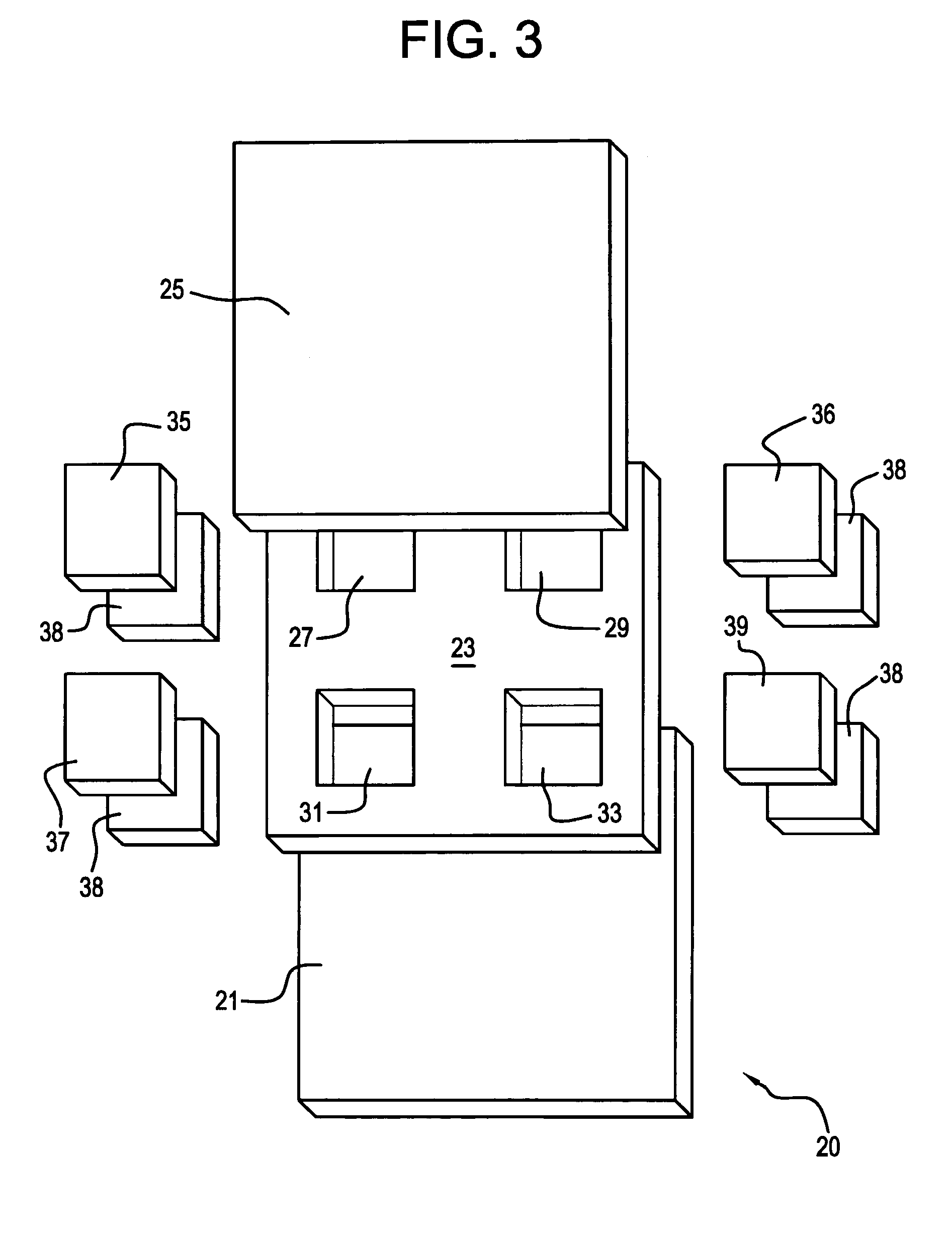
[0037]With reference to FIG. 3, the present invention is generally designated by the reference numeral 20 and is seen to include a backing plate 21, a middle plate 23, and a cover plate 25. The middle plate 23 has a plurality of cavities 27, 29, 31 and 33 formed therein through any desired manner including electrical discharge machining EDM processing or mechanical processing.

[0038]Ceramic tiles 35, 36, 37 and 39 and stiffening plates 38 are respectively received within the cavities 27, 29, 31 and 33, whereupon the cover plate 25 is placed thereover to encapsulate the ceramic tiles.

embodiment 40

[0039]With reference, now, to FIGS. 4–10, a further embodiment of the present invention is generally designated by the reference numeral 40 (see FIG. 10). The embodiment 40 includes a backing plate 41, a frame structure 43, and a cover plate 45. With reference to FIGS. 4–9, the manner of assembly of the frame structure 43 will be explained. With reference, first, to FIGS. 4 and 5, the frame structure 43 includes a backing plate 47 having a top surface 49 into which crossing grooves 51 and 53 are formed, of which the groove 51 is also seen in full lines in FIG. 5, and the groove 53 is shown in phantom therein.

[0040]With reference to FIGS. 6 and 7, a cross beam 55 has a bottom surface 57 inserted into the groove 51 and also includes an upper slot 59. With reference to FIGS. 8–9, a further cross beam 61 includes a bottom surface 63 designed to rest within the groove 53 and a slot 65 that is placed over the slot 59 in the beam 55 when assembled.

[0041]With reference to FIG. 10, the frame...


PUM

PropertyMeasurementUnit
elastic modulusaaaaaaaaaa

Abstract

A ceramic armor is disclosed in several embodiments. In a first embodiment, a metal base plate has a metal frame assembled on it having a central opening into which the ceramic material and stiffening plate are placed. A cover plate is placed over the frame to enclose the ceramic material on all sides. In a second embodiment, the frame has an open central area that has two crossing walls that define four sub-chambers. Four sets of ceramic material and stiffening plate are placed in the respective sub-chambers and a covering plate is placed over them. In a further embodiment, the frame has a plurality of cavities mechanically formed in it. A stiffening plate and a ceramic tile or plate are placed in each cavity and a cover plate is placed over the frame. The metal used to encapsulate the ceramic material may, if desired, comprise a Titanium alloy such as Ti-6Al-4V, and the ceramic material may comprise Silicon Carbide, Boron Carbide, Tungsten Carbide, Titanium Diboride, Aluminum Oxide or Aluminum Nitride. The stiffening plate is preferably made of a Ti—TiB cermet composite but may also be comprised of an armor ceramic such as WC, TiB2, Al2O3 or B4C. A hot pressing procedure is carried out on the armor to cause the metal to plastically deform about the encapsulated ceramic material.

Description

BACKGROUND OF THE INVENTION[0001]The present invention relates to ceramic armor and the method of making it by encapsulation including use of a stiffening plate adjacent to the metal backing plate. Ceramic containing armor has been shown to be an effective means to protect against a wide variety of ballistic threats because of its combination of high hardness, strength and stiffness along with low bulk density and favorable pulverization characteristics upon impact.[0002]However, ceramic material alone has been found to be ineffective against heavy ballistic threats such as Tungsten Carbide projectiles, and long rod heavy metal penetrators. Long rod projectiles can have a significant ratio of length to diameter, up to 40, and can travel at velocities up to or exceeding 1 mile per second. For the ceramic to effectively stop such threats, the ceramic material must be supported or encapsulated with another material such as metal or another composite capable of absorbing energy and prov...

Claims


Application Information

Patent Timeline
Patent Type & Authority Patents(United States)
IPC IPC(8): F41H5/02
CPCF41H5/0421Y10T428/12049
Inventor PALICKA, RICHARDASHKIN, DANIEL
Owner BAE SYST ADVANCED CERAMICS
Why Eureka
Try Eureka