Internal combustion engine

a technology of internal combustion engine and combustion chamber, which is applied in the direction of greenhouse gas reduction, steam generation using hot heat carriers, lighting and heating apparatus, etc., to achieve the effect of effectively utilizing the heat of the internal combustion engin

Inactive Publication Date: 2006-07-04
HONDA MOTOR CO LTD
View PDF6 Cites 46 Cited by
  • Summary
  • Abstract
  • Description
  • Claims
  • Application Information

AI Technical Summary

Benefits of technology

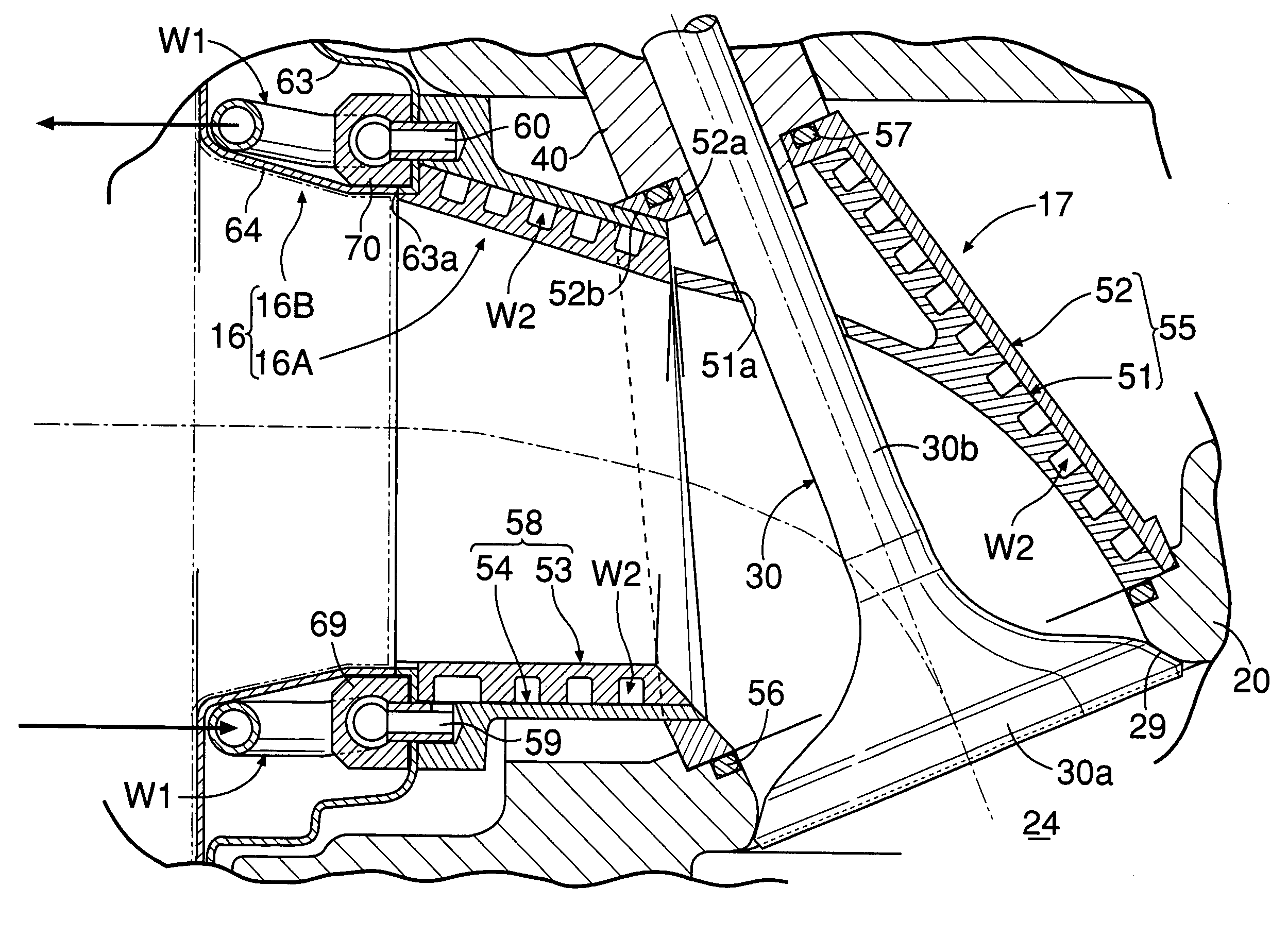
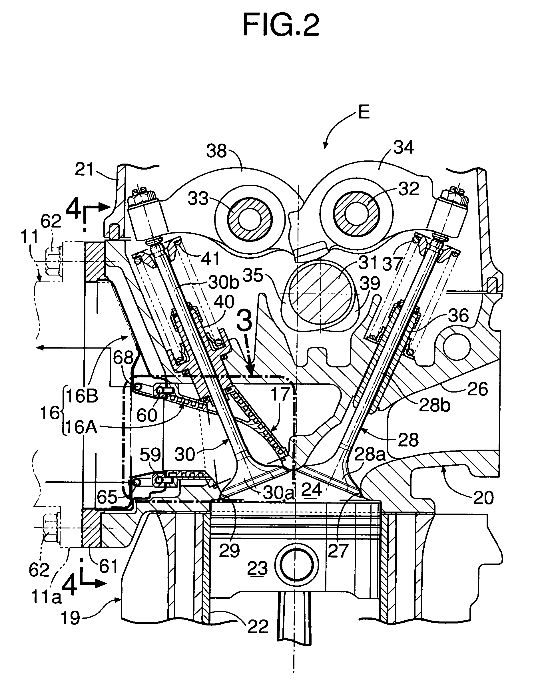
[0006]In accordance with this arrangement, since the surroundings of the exhaust port are covered by the water passage, it is possible to cool effectively the exhaust port, which has its temperature increased by high temperature exhaust gas discharged from the combustion chamber, and it is possible to recover effectively the heat of the exhaust gas with water flowing through the water passage.
[0018]In accordance with this arrangement, since the water that has passed through the water passage and has an increased temperature is used as the heat source for other auxiliary equipment, the waste heat of the internal combustion engine can be utilized effectively without being wastefully disposed of.

Problems solved by technology

However, in order to recover as much as possible of the waste heat of the internal combustion engine as high temperature steam, it is not enough only to make an evaporator provided in an exhaust passage exhibit its performance effectively by maintaining the temperature of the exhaust gas at a high temperature; it is also necessary to recover heat transferred from the exhaust port to the cylinder head and dissipated to the atmosphere.

Method used


Image

  • Internal combustion engine
  • Internal combustion engine
  • Internal combustion engine

Examples


Embodiment Construction

[0032]An embodiment of the present invention is explained below with reference to FIG. 1 to FIG. 11B.

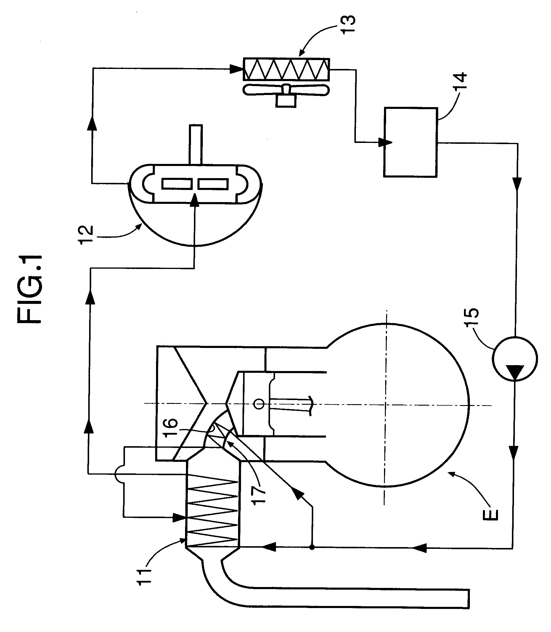
[0033]FIG. 1 shows the overall arrangement of a Rankine cycle system to which the present invention is applied.

[0034]The Rankine cycle system, which recovers the thermal energy of an exhaust gas of an internal combustion engine E and converts it into mechanical energy, includes a main evaporator 11 that heats water with exhaust gas discharged from the internal combustion engine E so as to generate high temperature, high pressure steam, an expander 12 that is operated by the high temperature, high pressure steam generated by the main evaporator 11 so as to generate mechanical energy, a condenser 13 that cools decreased temperature, decreased pressure steam that has completed work in the expander 12 so as to turn it back into water, a reservoir tank 14 for collecting water discharged from the condenser 13, and a supply pump 15 for pressurizing the water collected in the reservoir tank ...


PUM


Abstract

An internal combustion engine is provided in which an exhaust port communicating with a combustion chamber formed in a cylinder head is formed from independent exhaust ports, which are positioned on the upstream side, and a grouped exhaust port, in which the plurality of independent exhaust ports are combined. Water supplied from a supply pump passes through a water passage of the grouped exhaust port and a water passage of the independent exhaust ports while cooling the exhaust port, and a valve seat and valve guide on the periphery of the exhaust port, which have high temperatures, thus heating the water itself and thereby recovering waste heat of the internal combustion engine. The heated water carries out heat exchange with exhaust gas in an evaporator provided in an exhaust passage and turns into high temperature, high pressure steam, which drives an expander of a Rankine cycle system. It is thereby possible to maximize the recovery of heat transferred from the exhaust port to the cylinder head of the internal combustion engine.

Description

FIELD OF THE INVENTION[0001]The present invention relates to an internal combustion engine that includes an exhaust port within a cylinder head, exhaust gas being discharged from a combustion chamber into the exhaust port.BACKGROUND ART[0002]There is known from Japanese Patent Application Laid-open No. 2001-132444 an arrangement in which an exhaust port communicating with a combustion chamber of an internal combustion engine is formed from a pipe-shaped member, and by supporting this exhaust port within a cylinder head via a heat insulating layer, it is made difficult for exhaust gas heat to be transferred from the exhaust port to the cylinder head, thus maintaining the exhaust gas at as high a temperature as possible and thereby promoting the warm-up of the internal combustion engine and the early activation of an exhaust gas purification catalyst.[0003]However, in order to recover as much as possible of the waste heat of the internal combustion engine as high temperature steam, it...

Claims


Application Information

Patent Timeline
Patent Type & Authority Patents(United States)
IPC IPC(8): F02F1/36F01K23/06F01P3/02F01P3/14F01P3/20F01P3/22F02B75/02F02F1/38F02F1/42F02G5/02F22B1/18
CPCF01K23/065F01P3/02F01P3/14F01P3/22F02B75/02F02F1/38F02G5/02F22B1/1807Y02T10/166F01P2060/16Y02E20/30Y02T10/12
Inventor BABA, ATSUSHIENDOH, TSUNEOSHINOHARA, MASASHI
Owner HONDA MOTOR CO LTD
Why Eureka
Try Eureka