
Semiconductor device and its method for manufacturing it

a semiconductor and semiconductor technology, applied in the direction of printed circuit parts, non-conductive materials with dispersed conductive materials, printed element electric connection formation, etc., can solve the problems of difficult to fill the holes having the bottoms, cracks or the like, and large risk of semiconductor chips b>101/b>, so as to reduce the effect of reducing the damage of semiconductors

Inactive Publication Date: 2006-07-04
SONY CORP
View PDF16 Cites 71 Cited by
  • Summary
  • Abstract
  • Description
  • Claims
  • Application Information

AI Technical Summary

Benefits of technology

[0012]It is another object of the present invention to provide a semiconductor device which realizes a thinner device and can increase a capacity while realizing the thinner device, a layered semiconductor device using this semiconductor device and a method for manufacturing these semiconductor devices.
[0031]In another method for manufacturing a layered semiconductor device according to the present invention, the plural semiconductor devices each of which has a semiconductor chip cut extremely thinner than a usual semiconductor chip can be layered and a compact, and especially thin layered semiconductor device with high integration can be manufactured. Further, the semiconductor devices can be respectively connected together with high accuracy.

Problems solved by technology

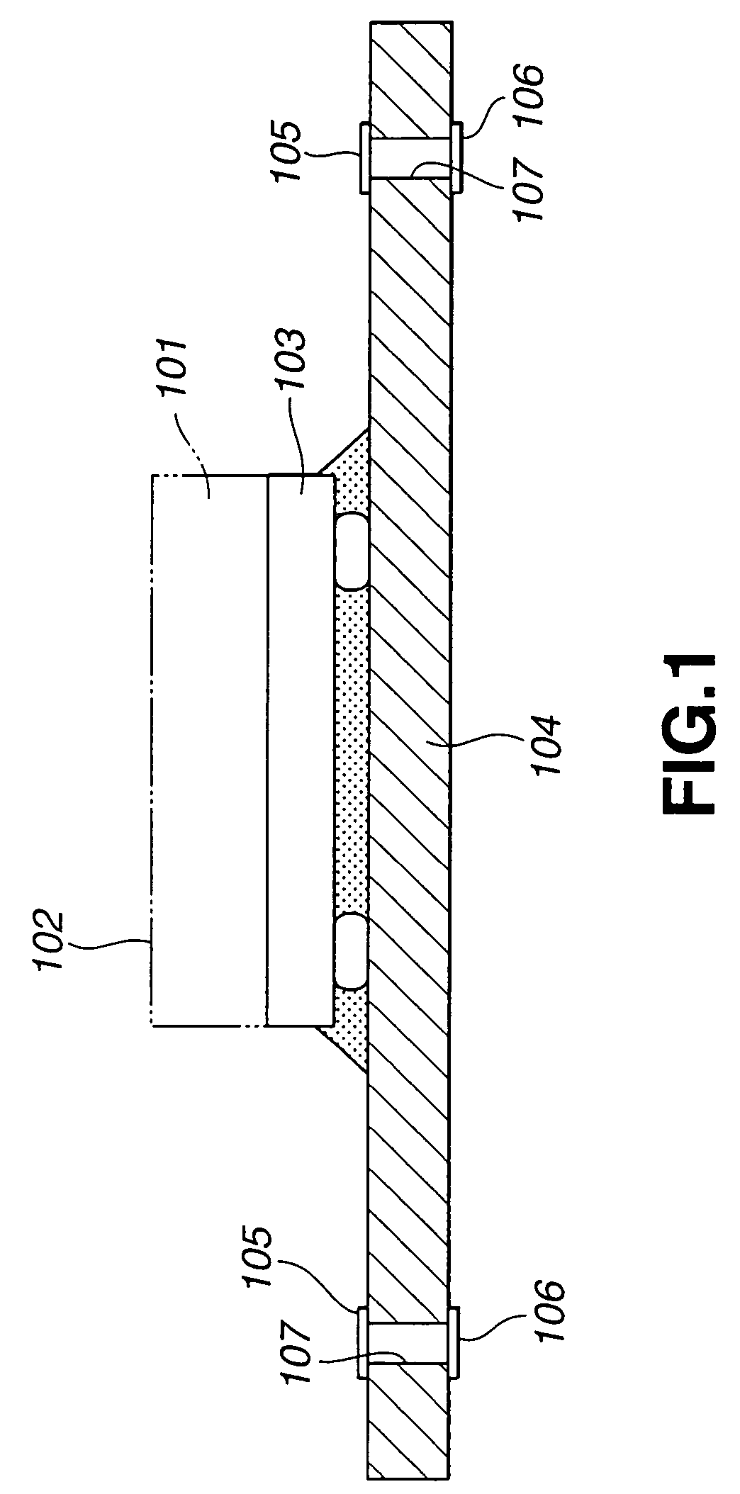
Thus, there arises a great risk that cracks or the like may be possibly formed on the semiconductor chip 101 and the semiconductor chip 101 may be broken.
The holes have bottoms, and it is very difficult to fill the holes having the bottoms with the soft solder so as not to supply air bubbles to the holes.
For instance, it is extremely difficult to supply the soft solder by a simple screen printing method.

Method used


Image

  • Semiconductor device and its method for manufacturing it
  • Semiconductor device and its method for manufacturing it
  • Semiconductor device and its method for manufacturing it

Examples


first embodiment

[0046]Firstly, the semiconductor device according to the present invention will be described by referring to FIG. 4. A semiconductor device shown in FIG. 4 has a substrate 2. On one surface side 2a of the substrate 2, a semiconductor chip 3 is mounted and inter-substrate connecting bumps 4 are provided. The semiconductor chip 3 and the inter-substrate connecting bumps 4 mounted on the substrate 2 are encapsulated by an encapsulating resin 5. The surfaces of the semiconductor chip 3, the inter-substrate connecting bumps 4 and the encapsulating resin 5 opposite to the substrate 2, that is, surfaces facing the front surface side of the semiconductor 1 in FIG. 4 serve as cut flat surfaces 3a, 4a and 5a, respectively. The cut flat surfaces 3a, 4a and 5a are all cut so as to be located in the same plane.

[0047]In the semiconductor device 1 shown in FIG. 4, the thickness D1 of the substrate 2 ranges from 100 m to 150 m. The thickness D2 from one surface 2a of the substrate 2 to the respecti...

second embodiment

[0048]Subsequently, the semiconductor device according to the present invention will be described by referring to FIG. 5. In a semiconductor device 1A shown in FIG. 5, a semiconductor chip 3 is mounted on the other surface side 2b of a substrate 2 as well as one surface side 2a and inter-substrate connecting bumps 4 are provided. That is, in the semiconductor device 1A, the semiconductor chips 3 are mounted and the inter-substrate connecting bumps 4 are provided on both the surfaces of the substrate 2. Also in this semiconductor device 1A, the semiconductor chip 3 and the inter-substrate connecting bumps 4 mounted on the other surface side 2b of the substrate 2 are encapsulated by an encapsulating resin 5 and the surfaces of the semiconductor chip 3, the inter-substrate connecting bumps 4 and the encapsulating resin 5 facing surface sides are all cut flat surfaces 3a, 4a and 5a, respectively so as to be located in the same plane.

[0049]In the semiconductor device 1A shown in FIG. 5, ...

third embodiment

[0080]Now, a semiconductor device according to the present invention will be described by referring to FIGS. 21 and 22.

[0081]In the semiconductor device 1B according to the third embodiment shown in FIGS. 21 and 22, through holes 9 and inter-substrate connecting bumps 4 provided in the semiconductor device 1A according to the second embodiment are exposed to the side surfaces of the substrate 2. That is, the through holes 9 and the inter-substrate connecting bumps 4 are formed so as to be visually seen from the side parts of the semiconductor device 1B in the direction of an arrow mark A in FIG. 21. When a part having one semiconductor chip 3 on each of both surfaces of the substrate 2 is formed as an individual piece in the steps of manufacturing the semiconductor device 1A shown in FIG. 5, the individual piece is formed by cutting parts where the through holes 9 and the inter-substrate connecting bumps 4 are located. When the individual piece is formed, parts outside the parts whe...


PUM

PropertyMeasurementUnit
Pressureaaaaaaaaaa
Electrical conductoraaaaaaaaaa
Surfaceaaaaaaaaaa

Abstract

A semiconductor device in which a semiconductor chip (3) is mounted on a substrate (2), comprising a substrate having electrodes (7, 8) for substrate-to-substrate connection disposed on both sides of the substrate and connected via a through hole (9), a semiconductor chip having an electrode connected to a wiring pattern arranged on the substrate and having a flat-cut face opposite to the face where the electrode is provided, a bump (4) for substrate-to-substrate connection provided on the electrode for substrate-to-substrate connection and having a flat-cut face opposite to the face facing the substrate, a sealing resin body (5) provided on the substrate, used for sealing the semiconductor chip and the bump for substrate-to-substrate, and having a flat-cut face opposite to the face facing the substrate, wherein the flat-cut face (3a) of the semiconductor chip, the flat-cut face (4a) of the bump for substrate-to-substrate, and the flat-cut face (5a) or the sealing resin body are flush with one another, and the semiconductor chip and the bump for disk recording medium except for the flat-cut faces are scaled in the sealing body.

Description

TECHNICAL FIELD[0001]The present invention relates to a semiconductor device and a method for manufacturing it, and more particularly to a layered semiconductor device and a method for manufacturing it.BACKGROUND ART[0002]In recent electronic devices, arrangements to realize compact forms and higher functions of them have been made. In order to make the electronic devices compact and obtain the higher functions of them, it has been demanded to mount semiconductor devices of large capacity with small mounting areas and small mounting volume as much as possible.[0003]For instance, in the electronic device using a semiconductor memory, an attempt has been made to make the device more compact with the increase of an amount of treated information. As the amount of information handled by the electronic device increases, it has been also demanded not only to increase the capacity of the semiconductor memory used for storing the information, but also to make the semiconductor memory mounted...

Claims


Application Information

Patent Timeline
IPC IPC(8): H01L21/44H01L21/48H01L21/50H01L23/02H01L23/12H01B1/22H01L21/56H01L23/31H01L23/498H01L25/065H01L25/10H01L25/11H01L25/18H05K1/09H05K3/40
CPCH01B1/22H01L21/56H01L21/563H01L23/3121H01L23/49816H01L25/065H01L25/0657H01L25/105H05K1/095H05K3/4069H01L24/29H01L2224/1134H01L2224/13099H01L2224/16225H01L2224/73203H01L2224/73204H01L2224/83101H01L2225/06517H01L2225/0652H01L2225/06541H01L2225/06586H01L2924/01004H01L2924/01005H01L2924/01015H01L2924/01029H01L2924/0103H01L2924/01033H01L2924/01046H01L2924/01047H01L2924/01049H01L2924/0105H01L2924/01078H01L2924/01079H01L2924/01082H01L2924/01088H01L2924/12044H01L2924/30105H05K2201/0355H05K2201/0382H05K2203/1461H01L2924/00013H01L2924/01006H01L2924/01023H01L2924/01024H01L2924/18161H01L2224/32225H01L2225/1023H01L2225/1058H01L2924/10253H01L2224/32145H01L2224/73253H01L2924/15321H01L2924/15331H01L2924/00014H01L2924/3512H01L2924/00H01L2924/00012H01L2924/181H01L2924/12042H01L2224/0401Y10T29/4935
Inventor KOIKE, TOSHIHIKOHONDA, MANABUKATO, MASUO
Owner SONY CORP
Learn More