Graphics system with just-in-time decompression of compressed graphics data

Inactive Publication Date: 2006-07-04
ORACLE INT CORP
View PDF5 Cites 65 Cited by
  • Summary
  • Abstract
  • Description
  • Claims
  • Application Information

AI Technical Summary

Benefits of technology

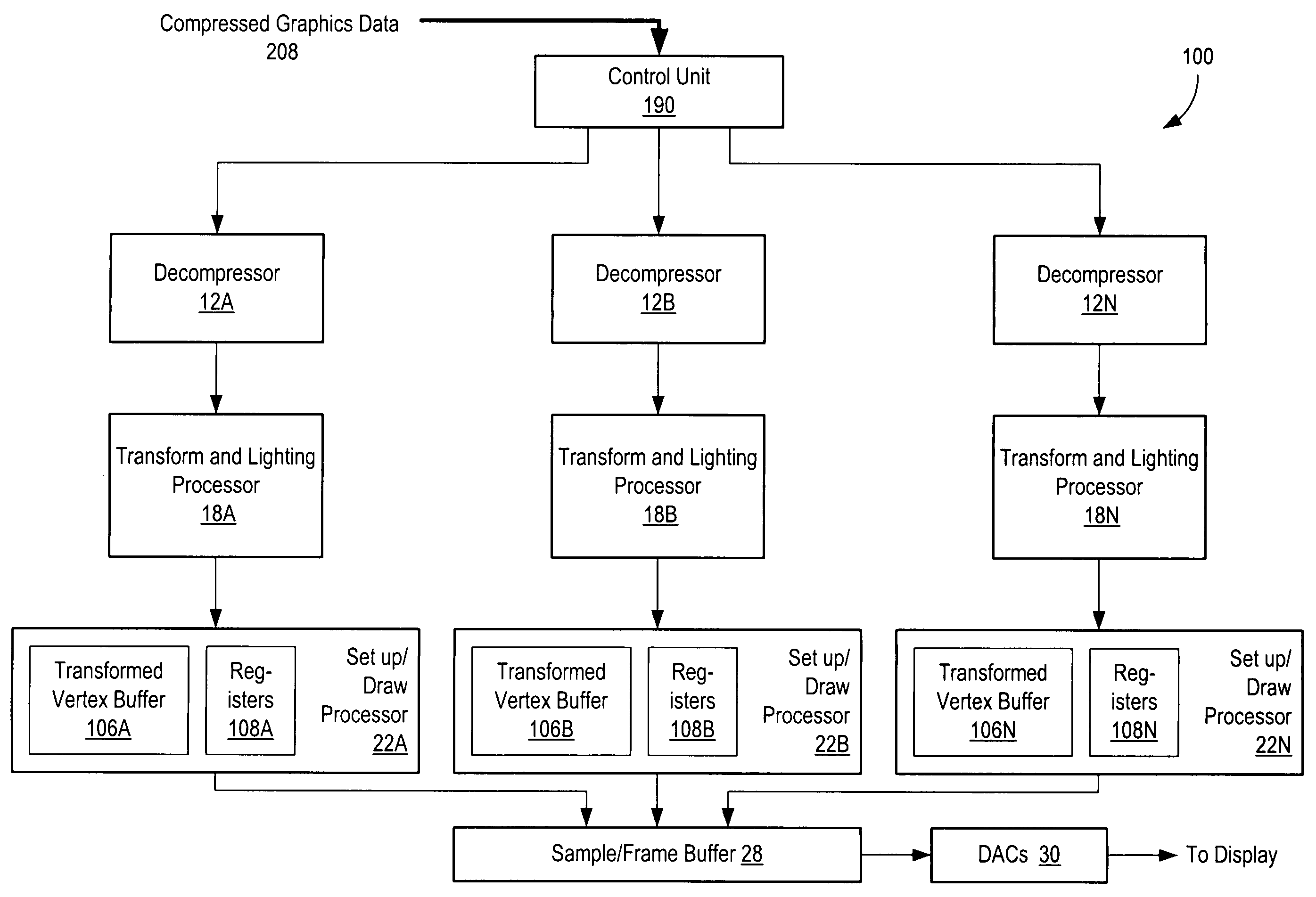
[0032]The problems outlined above may, in part, be solved by a graphics system capable of decompressing data blocks more efficiently. In some embodiments, multiple decompression pipelines (each having one or more decompressors) may be used in parallel to increase efficiency and lessen the load on any one decompressor. In one embodiment, a control unit may be used to selectively assign blocks of compressed vertex information to decompression pipelines. Each pipeline may th

Problems solved by technology

However, specifying all of the information associated with each vertex (e.g., xyz location,

Method used


Image

  • Graphics system with just-in-time decompression of compressed graphics data
  • Graphics system with just-in-time decompression of compressed graphics data
  • Graphics system with just-in-time decompression of compressed graphics data

Examples


Embodiment Construction

[0062]A graphics system according to the present invention may be used to achieve improved performance by reducing redundant processing. Advantageously, compressed geometry data may still be utilized by the system. Before describing the system and related method in detail, the overall environment in which the present invention may be practiced will be described.

Computer Network—FIG. 10

[0063]FIG. 10 depicts an example computer network. The computer network comprises a server 60 that is configured to convey compressed 3D geometry data to clients 70A–C. In some embodiments, server 60 may generate the compressed 3D geometry data in real time. In other configurations, the 3D geometry data may be generated off line. The compressed 3D geometry data may be conveyed to clients 70A–C in a number of different manners. For example, server 60 may transmit the compressed 3D geometry data via a physical communications network 68. Communications network may include Internet links, cable links, and ...


PUM


Abstract

A graphics system and method for increasing efficiency of decompressing blocks of compressed geometry data and reducing redundant transformation and lighting calculations is disclosed. Multiple decompression pipelines are used to increases the decompression speed. A control unit receives blocks of compressed geometry data information and selectively routes them to a plurality of decompression pipelines. Each decompression pipeline is configured to decompress the blocks into a set of vertices. The reduction in redundant calculations is accomplished by delaying the formation of geometric primitives until after transformation and lighting has been performed on the vertices. Transformation and/or lighting are performed independently on a vertex-by-vertex basis without reference to which geometric primitives the vertices belong to. After transformation and or lighting, geometric primitives may be formed utilizing previously generated connectivity information. The connectivity information may include mesh buffer references, vertex tags, or other types of information.

Description

FIELD OF THE INVENTION[0001]The present invention relates to computer graphics systems, and more particularly, to decompressing and rendering compressed three-dimensional geometry data.DESCRIPTION OF THE RELATED ART[0002]In recent years, demand for high performance graphics systems that can render complex three-dimensional (3D) objects and scenes has increased substantially. This increase is at least in part due to new applications such as computer-generated animation for motion pictures, virtual reality simulators / trainers, and interactive computer games. These new applications place tremendous demands upon graphics systems. One area in which particularly high demands are placed on graphics systems is bandwidth. This is because 3D graphics data may be several orders of magnitude larger than comparable 2D graphics data. For example, simple 2D graphics data may simply include color information for each pixel displayed. In contrast, 3D graphics data may include x,y,z position informat...

Claims


Application Information

Patent Timeline
IPC IPC(8): G06T15/00
CPCG06T9/00G06T15/50G06T15/04
Inventor DEERING, MICHAEL F.TREMBLAY, MARCCHAN, JEFFREY
Owner ORACLE INT CORP
Why Eureka
Try Eureka