Methods and apparatus for bridging different video formats

a technology of video signal and bridging method, which is applied in the field of video signal bridging process, can solve the problems of affecting the accuracy of the bridging process, the inability to match the the inability to achieve the matching of input and output clock rate, so as to achieve the effect of more precision

Inactive Publication Date: 2006-07-04
MAGIC PIXEL
View PDF56 Cites 25 Cited by
  • Summary
  • Abstract
  • Description
  • Claims
  • Application Information

AI Technical Summary

Benefits of technology

[0065]One technique by which frame rates are caused to match which is executed by the bridge logic includes determining the number of lines plus a number of pixels in input video stream as an input delay, counting input delay after an input vertical synchronization clock cycle or other fixed point in the input video stream, and issuing a “force” signal when input delay is reached. The first active line in a frame in the output video stream is started in synchronization with the output clock signal and after the force signal, such as upon the next output horizontal synchronization signal. The number of pixels in the input delay is zero in some embodiments and non-zero in some embodiments, allowing for more precision in the specification of input delay. Likewise the number of input lines in the input delay may be zero in some embodiments.
[0066]According to another technique, the bridge logic includes resources to set a lower bound input delay and upper bound input delay, wherein the lower and upper bound input delays are respective numbers of lines plus numbers of pixels in input video stream after an input vertical synchronization clock cycle or other fixed point in the input video stream. The first active line in a frame in the output video stream starts after a “back porch number” of lines in output video stream after the output vertical synchronization clock cycle or other fixed point in the output video stream. A number of “front porch” lines is inserted in the output video stream after a last active line in the frame, and before the vertical synchronization signal starting a next frame, in the output video stream. The number of front porch lines is adjusted if the first active line in the frame in the output video stream is outputted before the lower bound input delay (output frame period is too short) or after the upper bound input delay (output frame period is too long). In this way relative timing of the input video stream and output video stream can be adjusted with variations in the output and input clocks.

Problems solved by technology

Difficulties in bridging the formats arise because of non-integer ratios of the input frame size to the output frame size, as expressed for example in the parameters iV, iVDE, iH and iHDE, for the input video stream and oV, oVDE, oH and oHDE for the output video stream.
The difficulties are aggravated by the limitations of matching input and output clock rates used for the bridging.
However, the output clock frequency Fod cannot be precisely controlled.
Such an additional buffer would take a huge amount of area on the bridge chip, and make it much more expensive.
Thus, the overall system can not meet the three requirements (1) that the line buffer not overflow / underflow, (2) that the frame rate of the input match the frame rate of the output, and (3) that the residue line not be smaller than the device minimum.
In these cases, the width of residue line is unstable due to an unstable Fid.
The residue line problem is worse where the destination device is unable to handle lines that are less than a minimum specified parameter.
Another problem which occurs in the prior art arises from the fact that the actual output frequency for the display Fod will fluctuate simply because of the short-term variation of the clock generator.
Prior art systems address this problem by increasing the size of the line buffers, increasing chip cost.
This causes unstable display output.
It can be seen that the problem of bridging an input video format to an output video format in an economical manner which provides stable display output for a range of output devices is complex.
As the number of types of output device increases, the problem is becoming more prevalent.

Method used


Image

  • Methods and apparatus for bridging different video formats
  • Methods and apparatus for bridging different video formats
  • Methods and apparatus for bridging different video formats

Examples


Embodiment Construction

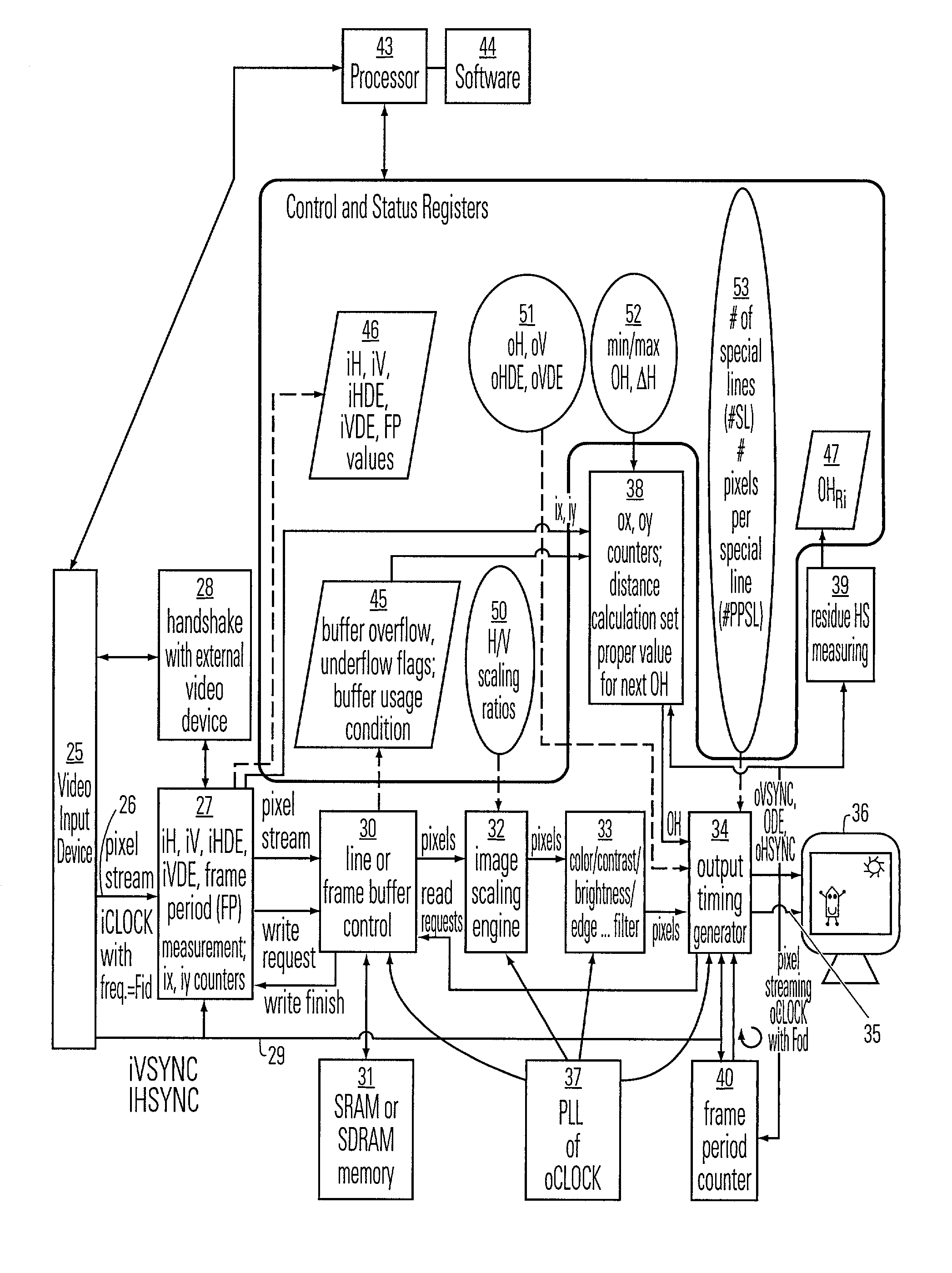
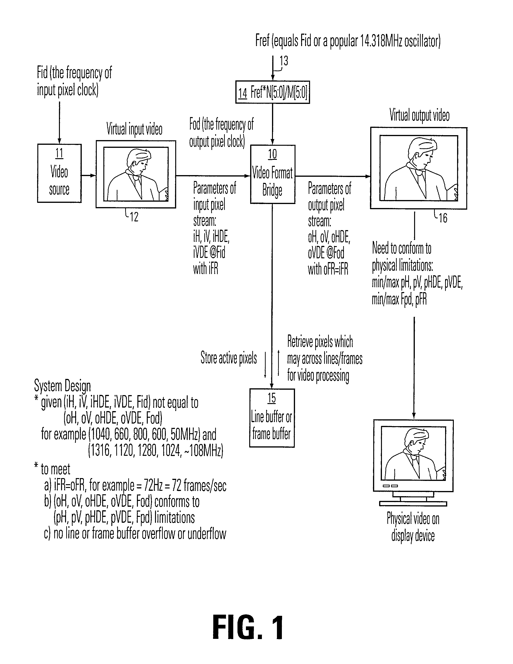
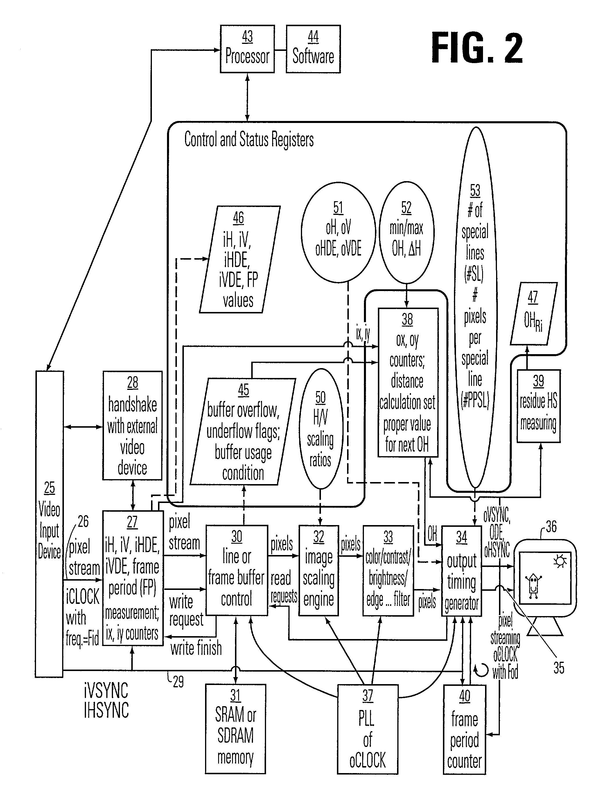
[0105]A detailed description of embodiments of the present invention is provided with respect to the figures. FIG. 1 is a basic illustration of system that includes a video format bridge 10 according to the present invention. The system accepts input from a video source 11, which is characterized as a virtual input video frame 12. The video source 11 has a input pixel clock Fid, and outputs the input video stream with the parameters iH, iV, iHDE, iVDE for a given input pixel clock Fid and input frame rate iFR.

[0106]A reference clock is supplied on line 13 to the clock generator 14. The reference clock may be supplied by crystal oscillator, such as the popular 14.318 MHz oscillator in common use, or may be derived from the input pixel clock Fid. The clock generator is implemented using a frequency divider having six bits of accuracy in this example. Thus, the clock frequency of the output video stream Fod is equal to the reference frequency Fref times the six bit value N[5:0] divided...


PUM


Abstract

A video format bridge employs a plurality of techniques to insure that the line buffer does not suffer underflow or overflow conditions, and that the output frame rate matches the input frame rate. The bridge handles the problem of residue lines, addresses fluctuations in the input and output clock rates, and allows adjustment of the ratio of the input and output the number of lines per frame or number of pixels per line so that output device specifications are not exceeded. A single integrated circuit may provided which is adapted to perform a plurality of techniques, and includes resources by which the user is able to enable and disable such techniques as needed for the particular bridging operation being executed. Bridge logic produces an output video stream which has an output frame rate matching the input frame rate, and in which the output frame has at least one of a variable number of pixels per line within an output frame, and/or a variable number of lines per frame among output frames in a set of more than one output frames.

Description

BACKGROUND OF THE INVENTION[0001]1. Field of the Invention[0002]The present invention relates to the process of bridging a video signal from one format to another; and more particularly to processes and structures used in integrated circuits provided for that purpose.[0003]2. Description of Related Art[0004]There is an on-going transition from raster-scan CRT display devices to pixel-based displays, like liquid crystal display LCD monitors, plasma TVs and projection TVs. Pixel-based display devices have strict timing specifications, typically stricter then the typical cathode ray tubes CRT's used in standard televisions and computer monitors.[0005]Conditions that must be met for successful bridging include the forcing of the input frame rate iFR to match the output frame rate oFR, and that the buffer used during the bridging not be subject to overflow or underflow conditions. Further it is desirable that the buffer used for bridging be small as possible to save each chip area and im...

Claims


Application Information

Patent Timeline
Patent Type & Authority Patents(United States)
IPC IPC(8): H04N7/01G09G3/20G09G5/00G09G5/391
CPCG09G5/008H04N7/0105H04N7/01G09G5/391
Inventor CHEN, CHANG-LUNHUANG, HSIAO-MINGWEI, MENG-HSIU
Owner MAGIC PIXEL
Why Eureka
Try Eureka