Bidirectional optical triplexer

a bidirectional optical and triplexer technology, applied in multiplex communication, electromagnetic repeaters, instruments, etc., can solve the problems of reducing affecting the performance of the system, so as to reduce the crosstalk between elements and reduce the size of the platform

Inactive Publication Date: 2006-07-04
SAMSUNG ELECTRONICS CO LTD
View PDF6 Cites 60 Cited by
  • Summary
  • Abstract
  • Description
  • Claims
  • Application Information

AI Technical Summary

Benefits of technology

[0020]Another object of the present invention is to reduce the crosstalk between elements.
[0021]Yet another object of the present invention is to reduce the size of a platform in order to make the bidirectional optical triplexer smaller.

Problems solved by technology

However, the conventional optical triplexer 100 described above has a problem in that a size of the platform 120, in which components are integrated, is enlarged because of the various components that are required for the optical triplexer 100.
In addition, since the filters cannot be perfectly manufactured, crosstalk may nevertheless occur.
This means that it is not possible to separate the optical signals by using only one filter.

Method used


Image

  • Bidirectional optical triplexer
  • Bidirectional optical triplexer
  • Bidirectional optical triplexer

Examples


first embodiment

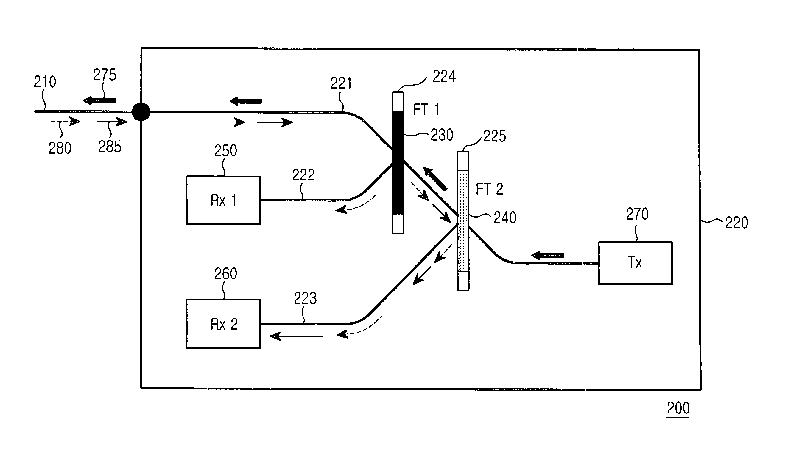
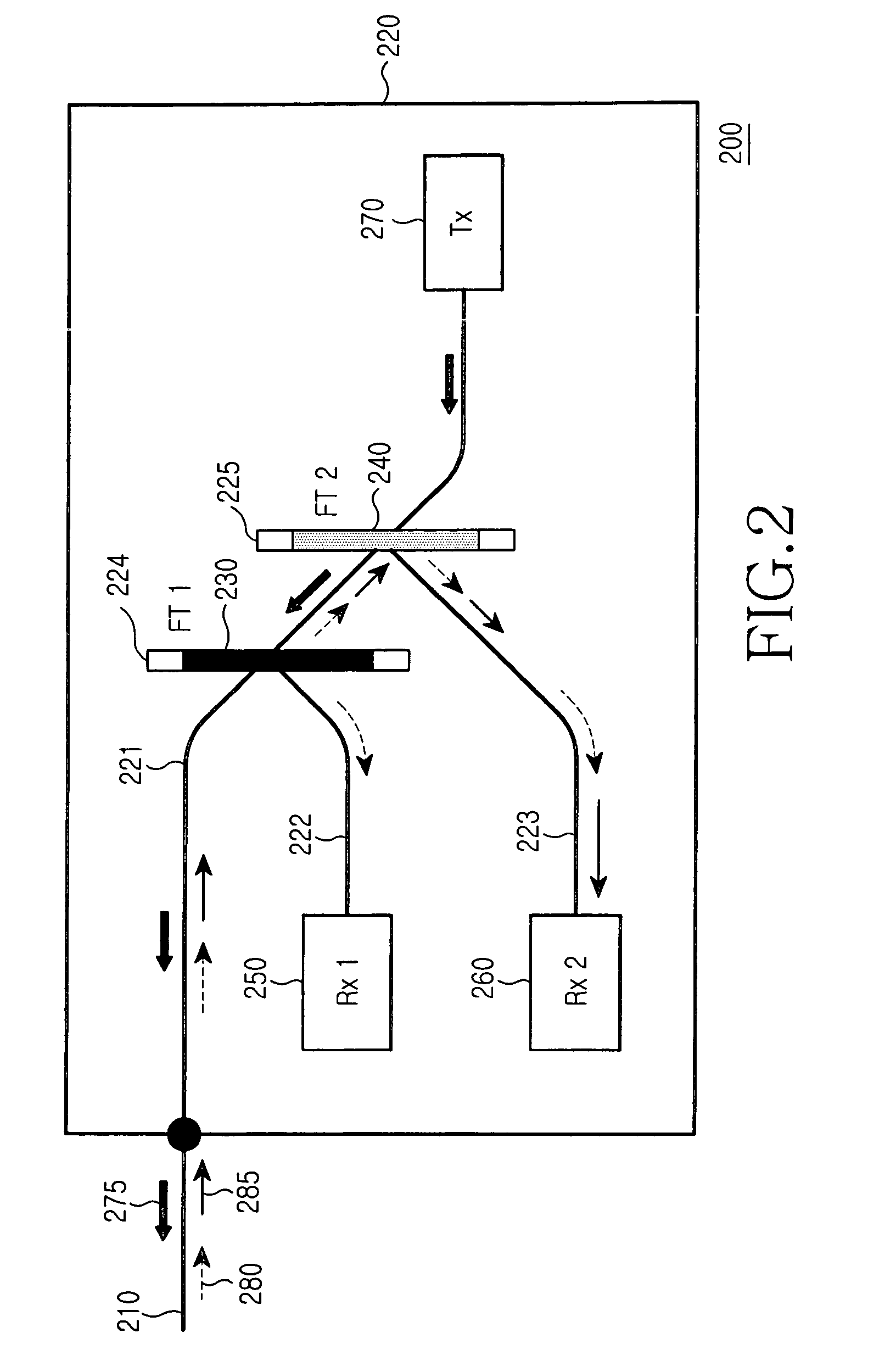
[0032]FIG. 2 is a diagram showing a bidirectional optical triplexer 200 according to the present invention. The optical triplexer 200 includes a platform 220, first and second filters 230 and 240, first and second optical receivers (Rxs) 250 and 260, and an optical transmitter 270. The optical triplexer 200 can be connected to an external optical waveguide 210. Also, the optical triplexer 200 can receive a first optical signal 280, which may be an analog video signal having about a 1550 nm wavelength, and a second optical signal 285, which may be a digital data signal having about a 1490 nm wavelength, through the external optical waveguide 210. In addition, the optical triplexer 200 transmits a third optical signal 275, which may be a digital data signal having about a 1310 nm wavelength, through the external optical waveguide 210.

[0033]The platform 220 includes a first optical path 221, which can be optically connected with the external optical waveguide 210, first and second tren...

second embodiment

[0044]FIG. 3 is a diagram showing a bidirectional optical triplexer 300 according to the present invention.

[0045]Referring to FIG. 3, the optical triplexer 300 includes a platform 320 which has first to third optical paths 321 to 323 and first and second trenches 324 and 325, first to third filters 330 to 350, first and second optical receivers 360 and 370, and an optical transmitter 380. When comparing the structure of the optical triplexer 300 with the structure shown in FIG. 2, there is one difference in that the optical triplexer 300 additionally has a third filter 350. Therefore, redundant descriptions will be omitted.

[0046]The platform 320 includes the first optical path 321, which may be optically connected with an external optical waveguide 310, first and second trenches 324 and 325, which are spaced from each other on the first optical path 321, the second optical path 322, which extends from the first trench 324, and a third optical path 323, which extends from the second ...

third embodiment

[0049]FIG. 4 is a diagram showing a bidirectional optical triplexer 400 according to the present invention. FIG. 5a is a graph representing the reflection characteristic of the second filter 440. The optical triplexer 400 includes a platform 420 which has first to third optical paths 421 to 423 and first and second trenches 424 and 425, first to second filters 430 to 440, first and second optical receivers 450 and 460, and an optical transmitter 470. When comparing the structure of the optical triplexer 400 with the structure shown in FIG. 2, the optical triplexer 400 has only one difference in that the optical triplexer 400 uses the second filter 440 having different characteristic from that of the structure shown in FIG. 2. Therefore, redundant descriptions will be omitted.

[0050]The second filter 440 is positioned in the second trench 425. The second filter 440 reflects the second optical signal 485 proceeding through the first optical path 421. In addition, the second filter 440 ...


PUM


Abstract

A bidirectional optical triplexer is disclosed, which may be connected to an external optical waveguide and receives first and second optical signals having first and second wavelengths through the external optical waveguide, and transmits a third optical signal having a third wavelength. The triplexer includes a platform having first and second trenches spaced from each other on a first optical path optically connected with the external optical waveguide, a first filter positioned in the first trench for reflecting the first optical signal proceeding through the first optical path to a second optical path, and a second filter positioned in the second trench for reflecting the second optical signal proceeding through the first optical path to a third optical path. The triplexer also includes a first optical receiver for detecting the first optical signal proceeding through the second optical path, a second optical receiver for detecting the second optical signal proceeding through the third optical path, and an optical transmitter for outputting the third optical signal to the first optical path. The first and the second optical receiver may be aligned at a first side of the first and the second trenches and the optical transmitter may be aligned at a second side of the first and the second trenches. The first side is opposite to the second side about the first and second trenches.

Description

CLAIM OF PRIORITY[0001]This application claims priority to an application entitled “Bidirectional optical triplexer,” filed in the Korean Intellectual Property Office on Nov. 11, 2003 and assigned Serial No. 2003-79545, the contents of which are hereby incorporated by reference.BACKGROUND OF THE INVENTION[0002]1. Field of the Invention[0003]The present invention relates to FTTx systems (fiber to the x, x=Premises, Home, Business, etc.), and more particularly to a bidirectional optical triplexer applied to the FTTx systems.[0004]2. Description of the Related Art[0005]FTTH is an abbreviation of “fiber to the home”. Also, when ‘H’ of FTTH is replaced with ‘P’, FTTP means “fiber to the premises”. Although FTTx has different meanings depending on the last letter ‘x’ of FTTx, each of FTTH and FTTP has the same technical principle of transmitting data using optical fiber to a terminal connected to an optical communication network. FTTH system can be used to combine communication, broadcast...

Claims


Application Information

Patent Timeline
Patent Type & Authority Patents(United States)
IPC IPC(8): G02B6/28G02B6/12G02B6/122G02B6/34G02B6/42H04B10/00H04B10/2507H04B10/27H04B10/29H04J14/00H04J14/02
CPCG02B6/4246G02B6/12007G02B6/28
Inventor KIM, KYOUNG-YOUMJUNG, SUN-TAE
Owner SAMSUNG ELECTRONICS CO LTD
Why Eureka
Try Eureka