Method and system for performing crosstalk analysis

a crosstalk analysis and analysis method technology, applied in the field of methods, can solve the problems of victim wire switching too slowly, victim wire switching too quickly, and the intended operation of the ic to fail

Inactive Publication Date: 2006-07-04
CADENCE DESIGN SYST INC
View PDF5 Cites 158 Cited by
  • Summary
  • Abstract
  • Description
  • Claims
  • Application Information

AI Technical Summary

Problems solved by technology

If the victim wire improperly and unexpectedly leaves its stable state, this could cause the intended operation of the IC to fail.
As another example, if the current in an aggressor wire is in the same direction as the current in a nearby victim wire, the resultant crosstalk may cause the victim wire to switch too quickly.
On the other hand, if the current in an aggressor wire is in the opposite direction from the nearby victim wire, then the resultant crosstalk may cause the victim wire to switch too slowly.
In either case, the crosstalk effect may cause the IC to fail.
While this approach may be relatively accurate, the problem with this approach is that it is normally very expensive to run a full-chip simulation given the size, complexity, and number of components on modern IC designs.
Simulating an IC design having hundreds of thousands or millions of components could consume an inordinate amount of time and computing equipment.
As technology progresses and the complexity and number of components increase on typical designs, this approach becomes ever more impractical.
Unfortunately, while this simplistic solution that may be faster than a full-chip simulation, it may also result in inaccurate approximations of the true delay characteristics of the design, since this approach only considers capacitance when determining delay.
The problem is that if the delay characteristics are underestimated, then unexpected delays may cause the chip to fail.
However, if the delays characteristics are overestimated, this may cause the designer to over-design the chip to address “phantom” problems that do not truly exist in the chip design.

Method used


Image

  • Method and system for performing crosstalk analysis
  • Method and system for performing crosstalk analysis
  • Method and system for performing crosstalk analysis

Examples


Embodiment Construction

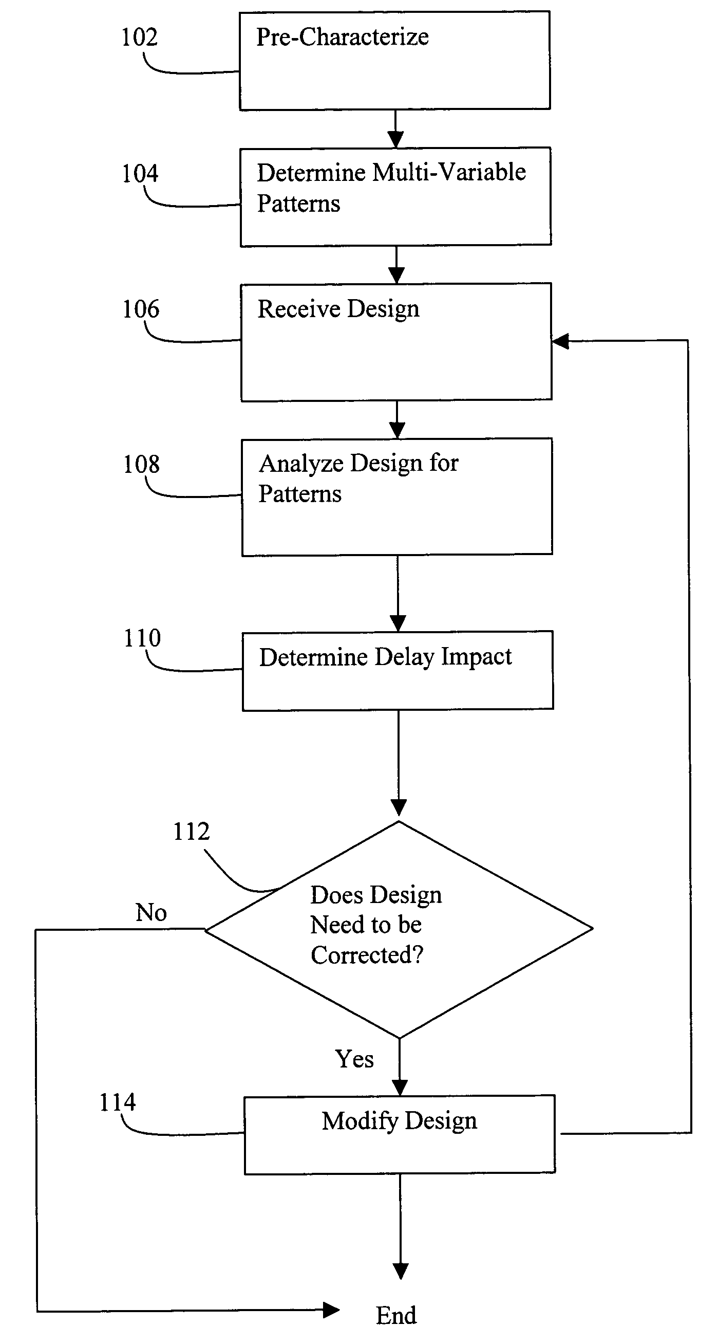
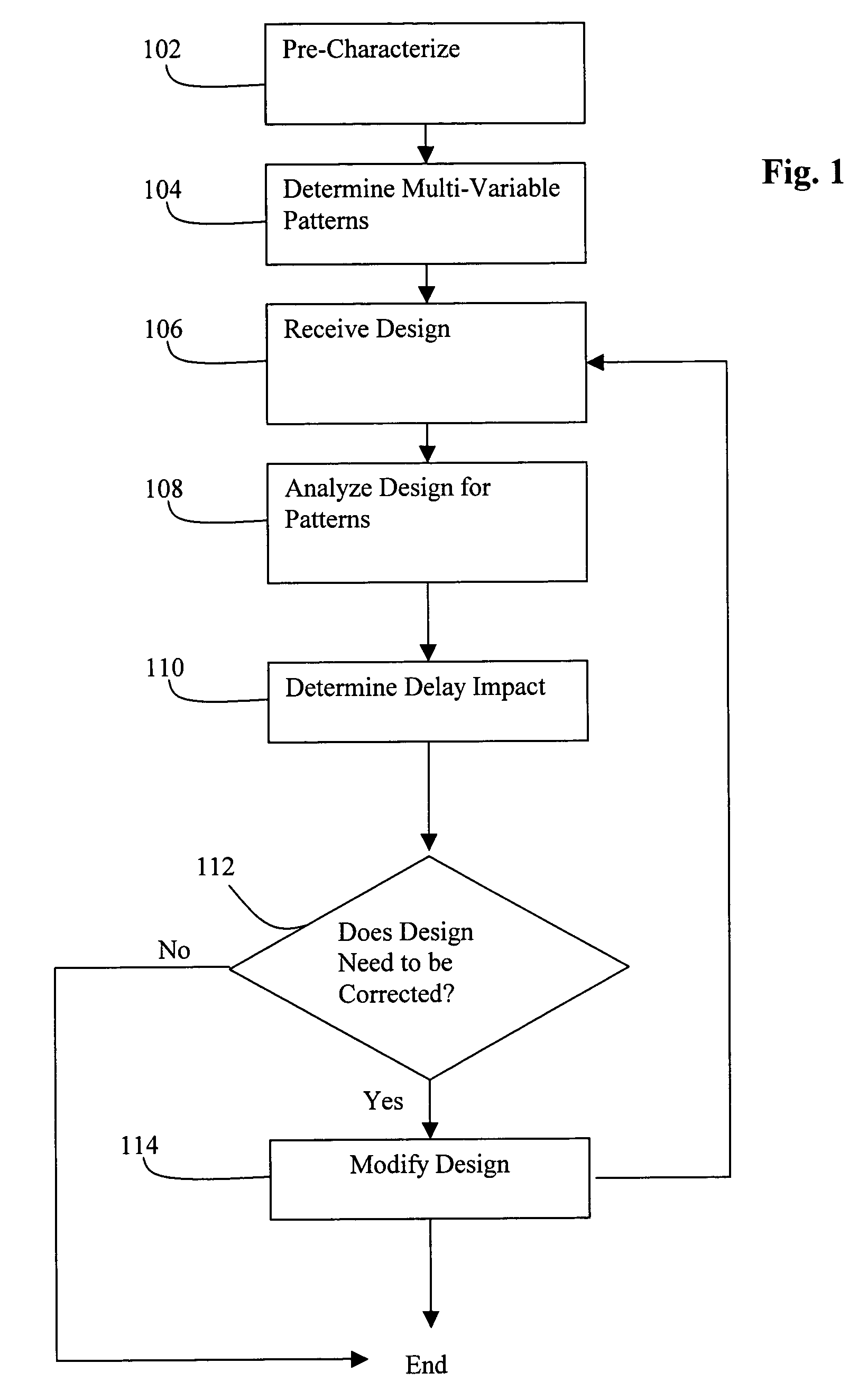
[0018]The present invention is directed to a method and mechanism for performing crosstalk and signal integrity analysis. In an embodiment, multi-variable pattern analysis is performed to implement the crosstalk analysis. Generally, this approach is performed by determining a set of multi-variable patterns corresponding to characteristics related to crosstalk effects. Each of these patterns can be analyzed and associated with a delay impact. Once an IC design is ready to be analyzed, the design is reviewed to determine whether any of the pre-characterized patterns are identified. The delay impact can therefore be readily determined from identifying these patterns.

[0019]FIG. 1 shows a flowchart of a process for crosstalk analysis according to an embodiment of the invention. At 102, device-level pre-characterization is performed. This action can be accomplished by performing device-level simulations / modeling that are run by systematically modifying the value of variables that are to b...


PUM


Abstract

Disclosed is an improved approach for performing crosstalk and signal integrity analysis in which multiple variables are taken into account when analyzing the effects of on-chip crosstalk, such as for example coupled wire length, ration of coupling capacitance, and aggressor and victim driver types. Rather than performing a full-chip simulation, the potential crosstalk effects can be pre-characterized by performing simulation / modeling over specific net portions by systematically changing the values of these multiple variables. A set of patterns characterized from the variables are formed from the modeling. During the analysis process, the IC design is checked of the presence of the patterns, from which is produced the expected delay impact for crosstalk in the design.

Description

CROSS-REFERENCE TO RELATED APPLICATIONS[0001]This application claims the benefit of U.S. Provisional Application No. 60 / 407,440, entitled “METHOD AND SYSTEM FOR PERFORMING CROSSTALK ANALYSIS”, filed Aug. 30, 2002, which is hereby incorporated by reference in its entirety.BACKGROUND AND SUMMARY[0002]The present invention relates generally to electronic circuit design and manufacturing.[0003]A semiconductor integrated circuit (IC) has a large number of electronic components, such as transistors, logic gates, diodes, wires, etc., that are fabricated by forming layers of different materials and of different geometric shapes on various regions of a silicon wafer. The design of an integrated circuit transforms a circuit description into a geometric description called a layout. The process of converting specifications of an integrated circuit into a layout is called the physical design. After the layout is complete, it is then checked to ensure that it meets the design requirements. The re...

Claims


Application Information

Patent Timeline
Patent Type & Authority Patents(United States)
IPC IPC(8): G06F17/50G06F17/00
CPCG06F17/5036G06F30/367
Inventor LI, JUNSPYROU, ATHANASIUSZHAO, HONGCHIU, HSIEN-YEN
Owner CADENCE DESIGN SYST INC
Why Eureka
Try Eureka