Optimized kinetic energy machine for excavating underwater rock

a kinetic energy machine and underwater rock technology, applied in mechanical machines/dredgers, soil shifting machines/dredgers, surface mining, etc., can solve the problems of excessive tooth and adaptor failure of prior art cutters of underwater rock, and achieve the effect of minimizing excavating parts failure, adequate tooth velocity, and increasing the capacity and effectiveness of rock excavators

Inactive Publication Date: 2006-07-11
MARILYN BARRY TRUSTEE OF THOMAS M TURNER TRUST F B O OF MOLLIE J MANGIAPIA 50 UNDIVIDED INTEREST MARILYN BARRY TRUSTEE OF THE THOMAS M TURNER TRUST F B O LESLIE S TURNER 50 UNDIVIDED INTEREST
View PDF6 Cites 0 Cited by
  • Summary
  • Abstract
  • Description
  • Claims
  • Application Information

AI Technical Summary

Benefits of technology

[0009]The primary object of this invention is to increase the capacity and effectiveness of rock excavators, particularly hydraulic dredge cutters. Another object of this invention is to minimize excavator parts failure. Yet another object of this invention is to assure adequate tooth velocity and cutting force to shatter the rock upon impact. Another object of this invention is to optimize the combined application of cutter force and tooth velocity on each tooth. A further object of this invention is to eliminate over-stress on cutter teeth and adaptors. Still yet another object of this invention is to minimize horsepower and cutting force while increasing rock-cutting capability. Another object of this invention is to reduce capital costs attendant to cutter horsepower (winches, flotation, and the like) while improving rock excavation. A broad objective of this invention is to encourage the dredging industry to utilize the concept of Kinetic Energy for hard rock dredging, since the old concepts based upon horsepower and unit pressure are inadequate. Other objects and advantages of the present invention will become apparent in the following descriptions, taken in connection with the accompanying drawings, wherein, by way of illustration and example, a preferred embodiment of the present invention is disclosed.
[0013]c) is subject to the same maximum stress, preferably but not essentially, less than the strength of the tooth and adaptor.As a result of the operating conditions noted above, the strength of each tooth and adaptor on the present invention can be designed to exceed the fixed maximum operating stress, and tooth and adaptor failure are thus reduced since stresses higher than the design capability are no longer caused by the intact rock it encounters. Further, the minimized need to replace broken teeth and adaptors reduces dredge downtime and the cost per cubic yard of dredged rock, including parts and labor. In addition, the high speed action of the present invention cutting teeth provides a smoother rock-cutting operation. Prior art cutters of underwater massive, hard rock often experience excessive tooth and adaptor failure, due to the positioning of a portion of the cutter teeth closer to the rotational axis where they are subject to higher drive forces. The prior art cutter teeth located closer to the cutter's rotational axis have less velocity, and therefore less Kinetic Energy for shattering rock. In contrast, the present invention cutter provides a simplified cutter with a simple hub, and several spokes extending between the hub and a rim, with all of the cutter's teeth being positioned on the rim at approximately the same distance from its rotational axis. As a result, each tooth present has the same peripheral velocity, is subject to the same maximum stress, and has adequate Kinetic Energy to shatter massive, hard rock upon impact. Thus, the present invention eliminates the excessive and premature failure experienced with prior art cutter teeth and adaptors, resulting in greater rock cutting capability, greater operational efficiency, less downtime, and reduced operational cost. Further, the simplified design of the present invention cutter, with its simple hub / spokes / rim configuration, reduces manufacturing costs.

Problems solved by technology

Prior art cutters of underwater massive, hard rock often experience excessive tooth and adaptor failure, due to the positioning of a portion of the cutter teeth closer to the rotational axis where they are subject to higher drive forces.

Method used


Image

  • Optimized kinetic energy machine for excavating underwater rock
  • Optimized kinetic energy machine for excavating underwater rock
  • Optimized kinetic energy machine for excavating underwater rock

Examples


Embodiment Construction

[0021]Detailed descriptions of the preferred embodiment are provided herein. It is to be understood, however, that the present invention may be embodied in various forms. Therefore, specific details disclosed herein are not to be interpreted as limiting, but rather as a basis for the claims and as a representative basis for teaching one skilled in the art to employ the present invention in virtually any appropriately detailed system, structure or manner.

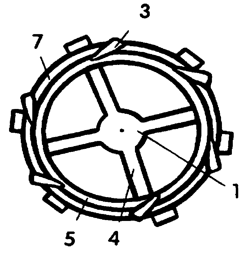
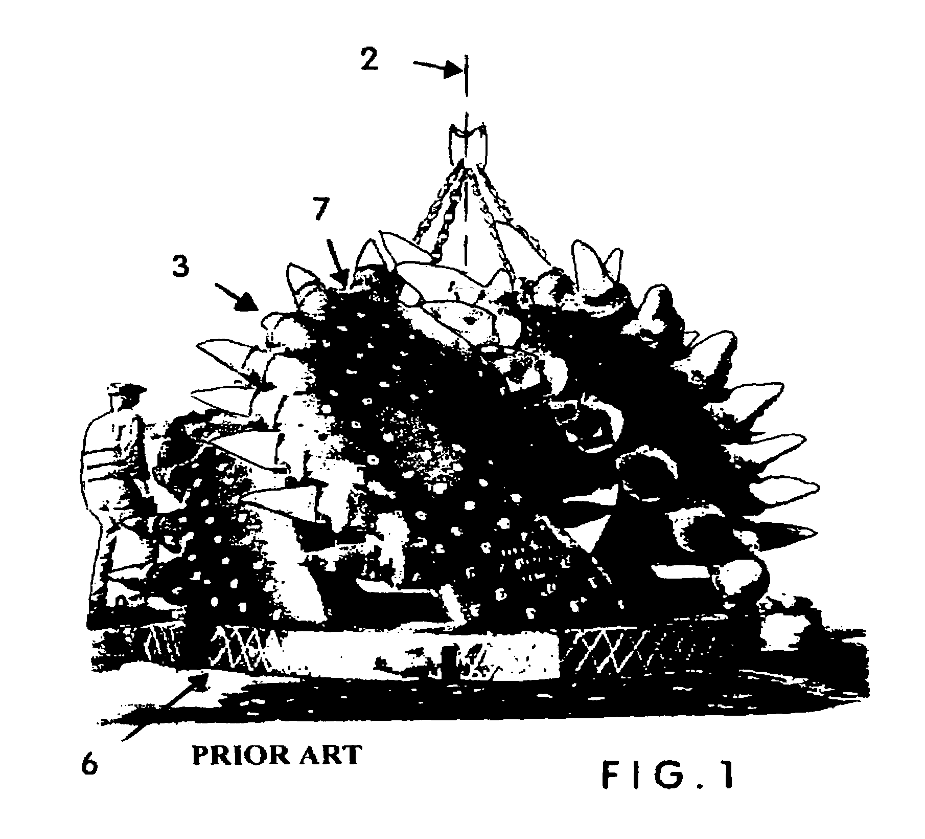
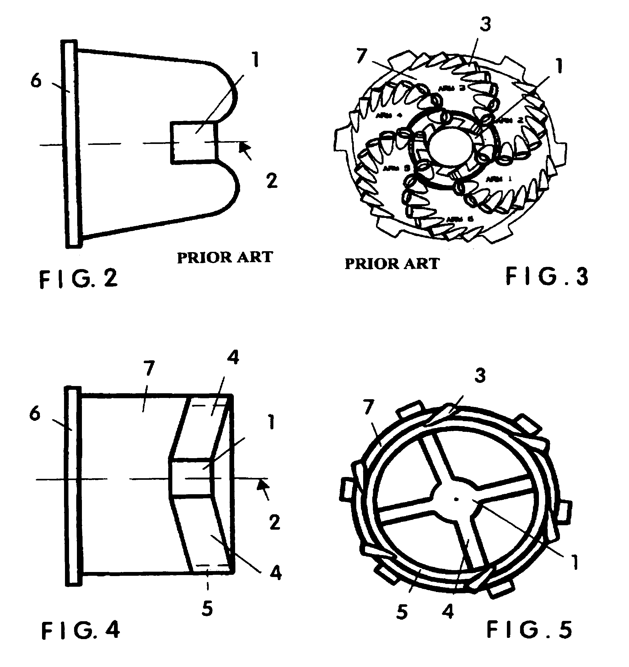
[0022]FIG. 1 shows a large, state-of-the-art dredge rock cutter which has had some success excavating underwater rock, but which has been hampered by excessive adaptor and tooth failure, resulting in high costs per cubic yard of rock excavated. The parts failure involved the first five teeth of the eight teeth on each blade, counting from the top (closed end) of the cutter. These teeth are closer to the cutter rotational axis 2 and are subject to higher drive forces than the teeth located farther from cutter rotational axis 2. For ex...


PUM


Abstract

A machine for improved excavation of underwater rock that eliminates failures due to over-stressed cutting teeth by positioning each hardened tooth for optimized Kinetic Energy. It has a plurality of blades, each with a hub and a plurality of spokes connecting the hub to a rim. Teeth are mounted on the leading edge of each blade approximately equidistant from the cutter axis of rotation, allowing each tooth to have the proper combination of velocity and cutting force required to shatter massive, hard rock. As a result, all teeth have approximately the same peripheral velocity; have adequate Kinetic Energy to shatter rock upon impact, and are subject to approximately the same maximum stress during rock excavation.

Description

CROSS REFERENCE TO RELATED APPLICATIONS[0001]This is a continuation of Provisional Patent Application entitled Dredge Cutterhead for Rock With Optimized Velocity Capability, Ser. No. 60 / 493,735, filed on Aug. 11, 2003 by the same inventor for the same subject matter.STATEMENT REGARDING FEDERALLY SPONSORED RESEARCH OR DEVELOPMENT[0002]Not ApplicableDESCRIPTION OF ATTACHED APPENDIX[0003]Not ApplicableBACKGROUND OF THE INVENTION—FILED OF THE INVENTION[0004]This invention relates generally to the field of excavating hard, massive rock, and more specifically to a cutterhead, hydraulic dredge, and method for excavating said rock underwater, whereby the configuration of the cutter and blade placement equidistant from the shaft assist in causing the application of proper Kinetic Energy to rock to assure its disintegration without premature failure of cutting blades. Previously, the industry has always relied upon the shearing strength of a cutter on the soil. However, rock does not shear, i...

Claims


Application Information

Patent Timeline
Patent Type & Authority Patents(United States)
IPC IPC(8): E21C50/00E21C25/06E02FE02F3/18E02F3/24E21C25/10
CPCE02F3/241E02F9/2866E02F3/9231
Inventor TURNER, THOMAS MILES
Owner MARILYN BARRY TRUSTEE OF THOMAS M TURNER TRUST F B O OF MOLLIE J MANGIAPIA 50 UNDIVIDED INTEREST MARILYN BARRY TRUSTEE OF THE THOMAS M TURNER TRUST F B O LESLIE S TURNER 50 UNDIVIDED INTEREST
Why Eureka
Try Eureka