Mirror fixing method and optical apparatus

a technology for fixing optical devices and mirrors, which is applied in the direction of mountings, mirrors, instruments, etc., can solve the problems of mirror b>101/b> coming away from the jig, stress distortion developing on the mirror surface, etc., and achieve the effect of high accuracy and stable performan

Inactive Publication Date: 2006-07-11
FUJITSU LTD
View PDF19 Cites 8 Cited by
  • Summary
  • Abstract
  • Description
  • Claims
  • Application Information

AI Technical Summary

Benefits of technology

[0015]Furthermore, for the mirror part in the above-mentioned optical apparatus, an aspherical surface mirror used in a variable wavelength dispersion compensator may be formed on the one face of the base plate. As a result, a possibility that the surface shape of th

Problems solved by technology

However, if the mirror 101 is fixed to the jig 102 by adhesive or mechanical fixing as with the above described conventional technique, there is a problem of stress distortion developing on the mi

Method used


Image

  • Mirror fixing method and optical apparatus
  • Mirror fixing method and optical apparatus
  • Mirror fixing method and optical apparatus

Examples


Embodiment Construction

[0030]Hereunder is a description of embodiments of the present invention based on the drawings.

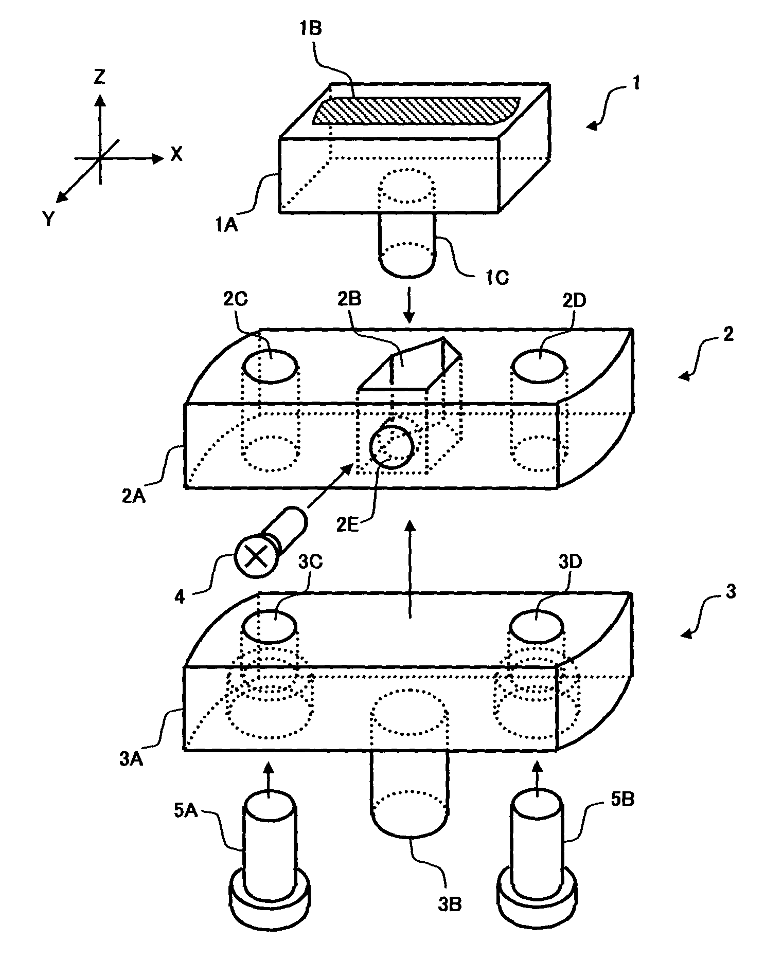
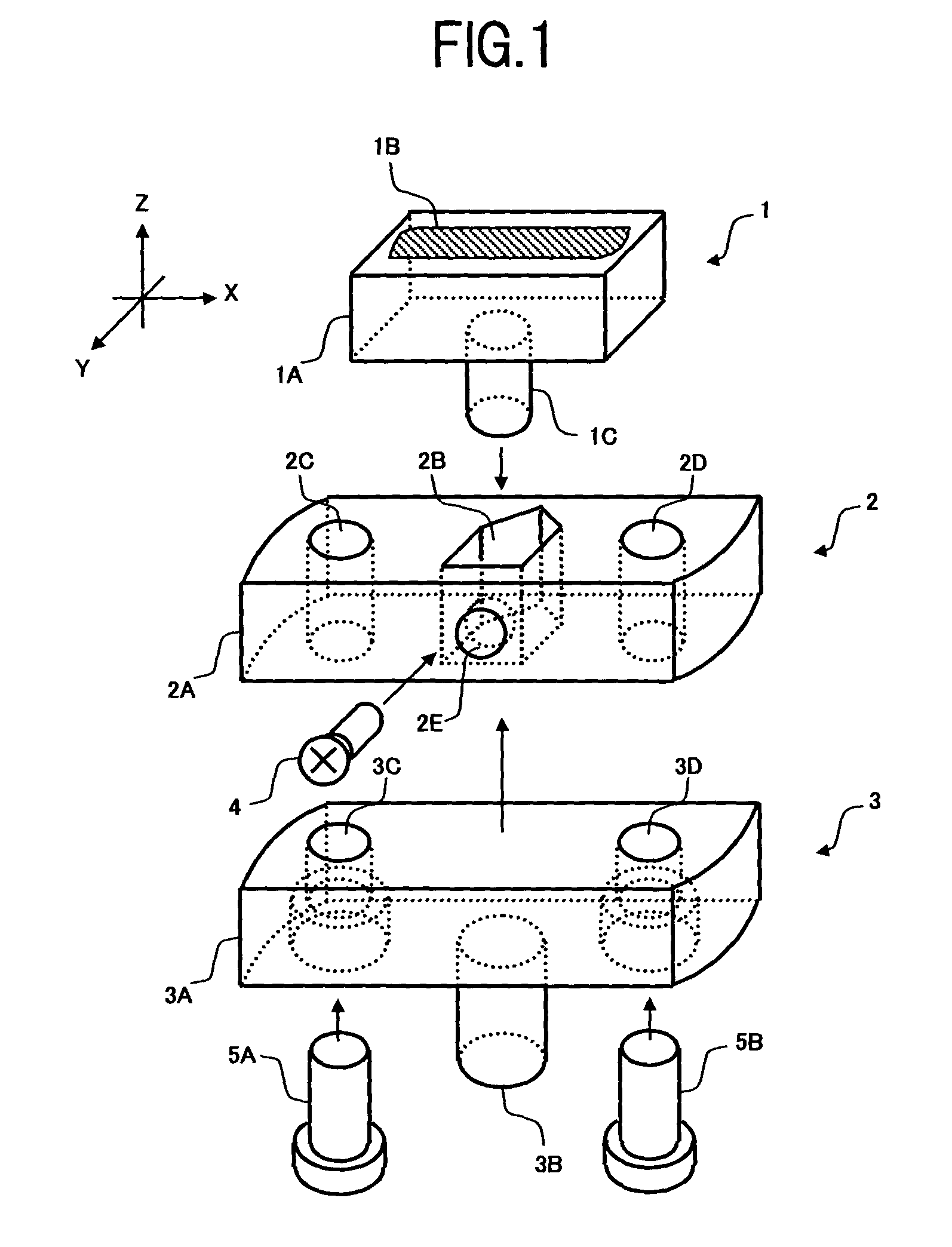
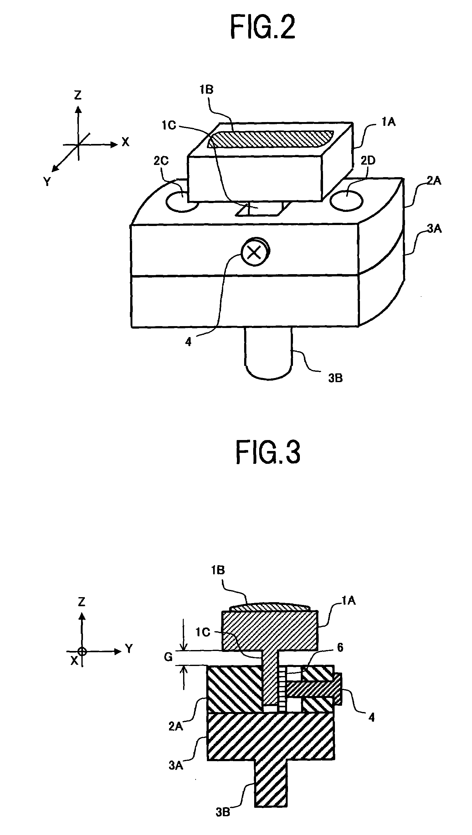
[0031]FIG. 1 is a perspective view of one embodiment of an optical apparatus to which a mirror fixing method of the present invention is applied, showing respective components in exploded form. FIG. 2 is a perspective view showing the appearance with the components of FIG. 1 assembled.

[0032]As shown in FIG. 1 and FIG. 2, the present optical apparatus comprises, for example, a mirror part 1, a first fixture 2 and a second fixture 3.

[0033]The mirror part 1 includes, for example, a base plate 1A formed using a material such as glass, plastics or the like, a mirror 1B formed by vacuum deposition of a metal or the like on one face (upper face in the figure) of the base plate 1A, and a protruding type boss 1C formed on the other face (lower face in FIG. 1) of the base plate 1A opposite the face on which the mirror 1B is formed. The mirror 1B is made with high accuracy so that its surface achieve...


PUM


Abstract

An object of the invention is to provide a mirror fixing method capable of reducing stress distortion of a surface of a mirror which constitutes an optical system, with hardly deforming a surface shape of the mirror. To this end, the present mirror fixing method is characterized in that a mirror part including a base plate formed with a mirror on one face thereof, is provided with a boss on the other face of the base plate opposite to the face on which the mirror is formed, and only the boss is fixed, so that the mirror part excluding the boss is not in contact with other members.

Description

BACKGROUND OF THE INVENTION[0001](1) Field of the Invention[0002]The present invention relates to a mounting technique for fixing mirrors that are used for constructing an optical system. In particular, the invention relates to a mirror fixing method for preventing stress distortion of mirror surface due to the fixing, and to an optical apparatus using the method.[0003](2) Related Art[0004]Normally, in order to construct an optical system, members such as a light source, lenses and mirrors are used to change an optical path or to collect lights. For example, as shown in FIG. 8, a mirror part 100 is sometimes used for changing a propagation direction of light emitted from a light source by 90°. In this mirror part 100, typically a mirror 101 with a mirror surface formed by vapor deposition of metal or the like on the surface of a base material made of glass, plastic, or the like, is fixed on a jig 102 for use. As a conventional method of fixing the mirror 101 on the jig 102, there is...

Claims


Application Information

Patent Timeline
IPC IPC(8): G02B5/08G02B7/192G02B6/34G02B7/182
CPCG02B6/29358G02B7/1825G02B7/182G02B6/29389
Inventor OKADA, HIDEOSAKATA, YUJIWAKANA, SHINICHIYAMAZAKI, YUJINKAWAHATA, YUICHIMITAMURA, NOBUAKI
Owner FUJITSU LTD
Why Eureka
Try Eureka