Heat emitting probe and heat emitting probe apparatus

a technology of heat emitting probes and probes, which is applied in the field of heat emitting probes and heat emitting probes, can solve the problems of limited thermal measurement of general sample surfaces on the nano-scale, the difficulty of controlling the diameter of holes to a value of several tens of nm or less, and the inability to achieve the recording density of conventional thermal recording media utilizing afm cantilevers, etc., to achieve the effect of increasing the recording density of thermal recording media

Inactive Publication Date: 2006-07-11
NAKAYAMA YOSHIKAZU +1
View PDF27 Cites 18 Cited by
  • Summary
  • Abstract
  • Description
  • Claims
  • Application Information

AI Technical Summary

Benefits of technology

[0016]Accordingly, it is an object of the present invention to provide a heat emitting probe and a heat emitting probe apparatus that increase the recording density of thermal recording media by using the tip end of a conductive nanotube such as a carbon nanotube, etc. as a heat emitting point instead of the tip end of a cantilever, so that the diameter of the fusion type holes can be reduced to a few nanometers.

Problems solved by technology

Since the hole diameter D is larger than this curvature radius, it is an extremely difficult task to control the hole diameter to a value of several tens of nm (nanometer) or less.
Accordingly, the recording density of conventional thermal recording media that can be achieved by means of a heat emitting holder utilizing an AFM cantilever has limitations.
Thus, in the past, problems exist not only in regard to the input and output of thermal recording media, but also in regard to thermal measurements of general sample surfaces on the nano-scale.
Nor has there been any means in the past for measuring the thermal conductivity distribution of sample surfaces on the nano-scale.

Method used


Image

  • Heat emitting probe and heat emitting probe apparatus
  • Heat emitting probe and heat emitting probe apparatus
  • Heat emitting probe and heat emitting probe apparatus

Examples


first embodiment

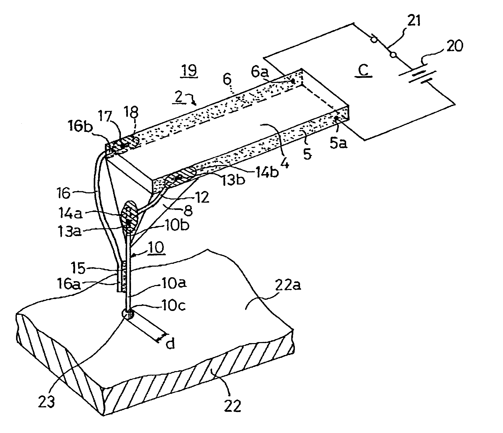
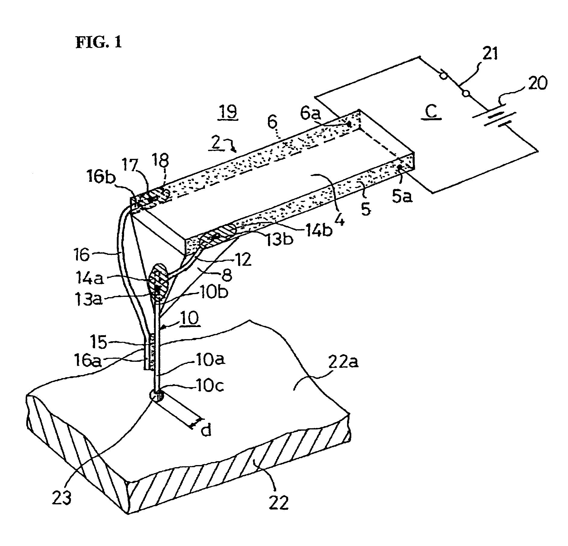
[0044]FIG. 1 shows the heat emitting probe of the present invention.

[0045]As in the conventional heat emitting probe, the heat emitting probe 19 is obtained by machining an AFM cantilever 2. The cantilever 2 is comprised of a cantilever portion 4 and a holder 8 (which is also referred to as a protruding portion or pyramid portion), and the holder 8 protrudes from the tip end of the cantilever portion 4.

[0046]Electrode films 5 and 6 are provided on both side surfaces of the cantilever portion 4. These films are formed by coating the side surfaces of the cantilever portion 4 with a conductive substance. A control circuit C is connected to the rear end portions of the electrode films 5 and 6 via contact points 5a and 6a. The control circuit C is comprised of a power supply 20 and a switch 21.

[0047]A conductive nanotube probe needle 10 is disposed on the holder 8. The conductive nanotube probe needle 10 is obtained by fastening the base end portion 10b of a conductive nanotube to the ho...

second embodiment

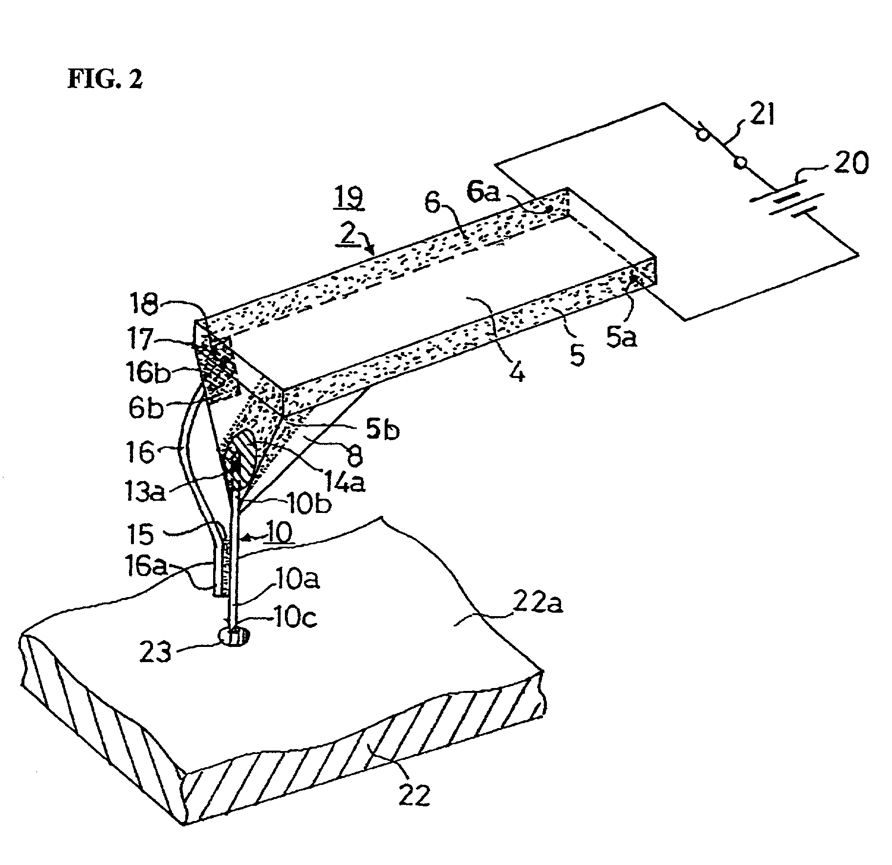
[0065]FIG. 2 shows the heat emitting probe of the present invention.

[0066]Elements that are the same as in the first embodiment are referred to with the same reference numerals, and a description of such elements is omitted. The second embodiment differs from the first embodiment in that joining electrode films 5b and 6b are formed on the holder 8. Of these two films, the joining electrode film 5b is installed instead of the conductive nanotube lead wire 12.

[0067]More specifically, the joining electrode film 5b is electrically continuous with the electrode film 5. Accordingly, voltage application to the conductive nanotube probe needle 10 is made possible merely by fastening the base end portion 10b of the conductive nanotube probe needle 10 by means of the coating film 14a. In other words, there is no need for the conductive nanotube lead wire 12, fused portion 13b or coating film 14b. Thus, the second embodiment is characterized in that it is possible to dispense with the process ...


PUM

PropertyMeasurementUnit
curvature radiusaaaaaaaaaa
diametersaaaaaaaaaa
diameteraaaaaaaaaa

Abstract

A heat emitting probe including a conductive nanotube probe needle with its base end fastened to a holder and its tip end protruded, a heat emitting body formed on the probe needle, a conductive nanotube lead wire fastened to the heat emitting body, and an electric current supply that causes an electric current to pass through the conductive nanotube lead wire and both ends of the probe needle. The tip end of the probe needle is thus heated by an electric current flowing through the heat emitting body. A heat emitting probe apparatus includes the above-described heat emitting probe, a scanning mechanism that allows the heat emitting probe to scan over a thermal recording medium, and a control circuit that causes the tip end of the probe needle to emit heat, thus recording extremely small hole patterns in the surface of a thermal recording medium.

Description

BACKGROUND OF THE INVENTION[0001]1. Field of the Invention[0002]The present invention relates to a heat emitting probe that performs thermal operations in a pinpoint fashion on the surface of a sample and to an apparatus that uses such a heat emitting probe.[0003]2. Prior Art[0004]Conventionally, magnetic recording media such as magnetic disks, etc., and optical recording media such as optical disks, etc. are widely used as recording media for information. In recent years, thermal recording media have begun to be developed.[0005]Such thermal recording media are obtained from a low-melting-point organic substance, and information is recorded on such media by forming fusion type holes in the surface thereof by means of heat. For example, a hole is defined as “1”, and the absence of a hole is defined as “0”; and information is recorded by series of these holes. Since the density at which information is recorded increases with a decrease in the diameter of these holes (hereafter referre...

Claims


Application Information

Patent Timeline
Patent Type & Authority Patents(United States)
IPC IPC(8): G01K7/00G01K3/00G01K7/16G01N25/18G01Q30/10G01Q60/00G01Q60/38G01Q60/40G01Q70/12G01Q80/00G11B9/00G11B9/14G11B11/00G11B11/03
CPCG11B9/14G11B9/1409B82Y10/00G11B11/007G01Q60/40G01Q80/00Y10S977/876G11B2005/0021Y10S977/863Y10S977/867
Inventor NAKAYAMA, YOSHIKAZUHARADA, AKIO
Owner NAKAYAMA YOSHIKAZU
Why Eureka
Try Eureka