Quick color change powder coating system

a spray system and powder coating technology, applied in the direction of coatings, colloidal chemistry details, chemistry apparatus and processes, etc., can solve the problems of affecting the quality of powder coating application, the longer the spray system is off-line, the longer it takes to clean the system, etc., to reduce the time, facilitate the cleaning of the booth, and reduce cross-contamination

Inactive Publication Date: 2006-07-11
NORDSON CORP
View PDF60 Cites 18 Cited by
  • Summary
  • Abstract
  • Description
  • Claims
  • Application Information

AI Technical Summary

Benefits of technology

[0027]Additionally, an inventive spray booth explosion door is provided. The explosion door has a first section hingedly attached to a wall and in communication with the cyclone inlet. It is operable to vent the inlet of the cyclone in the event of a first over-pressure condition within the booth, such as caused by a deflagration. The explosion door has a second, larger section hingedly attached to the booth wall and operable to vent the cyclone in the event of a second, larger over-pressure condition within the cyclone. The hinges retain or capture the door sect...

Problems solved by technology

When a plurality of pumps, suction tubes and powder spray devices are employed, output can vary between pumps and can randomly surge, affecting powder coating application quality.
However, the longer it takes for the cleaning process to complete, the longer the spray system is off-line.
Hence, if the...

Method used


Image

  • Quick color change powder coating system
  • Quick color change powder coating system
  • Quick color change powder coating system

Examples


Embodiment Construction

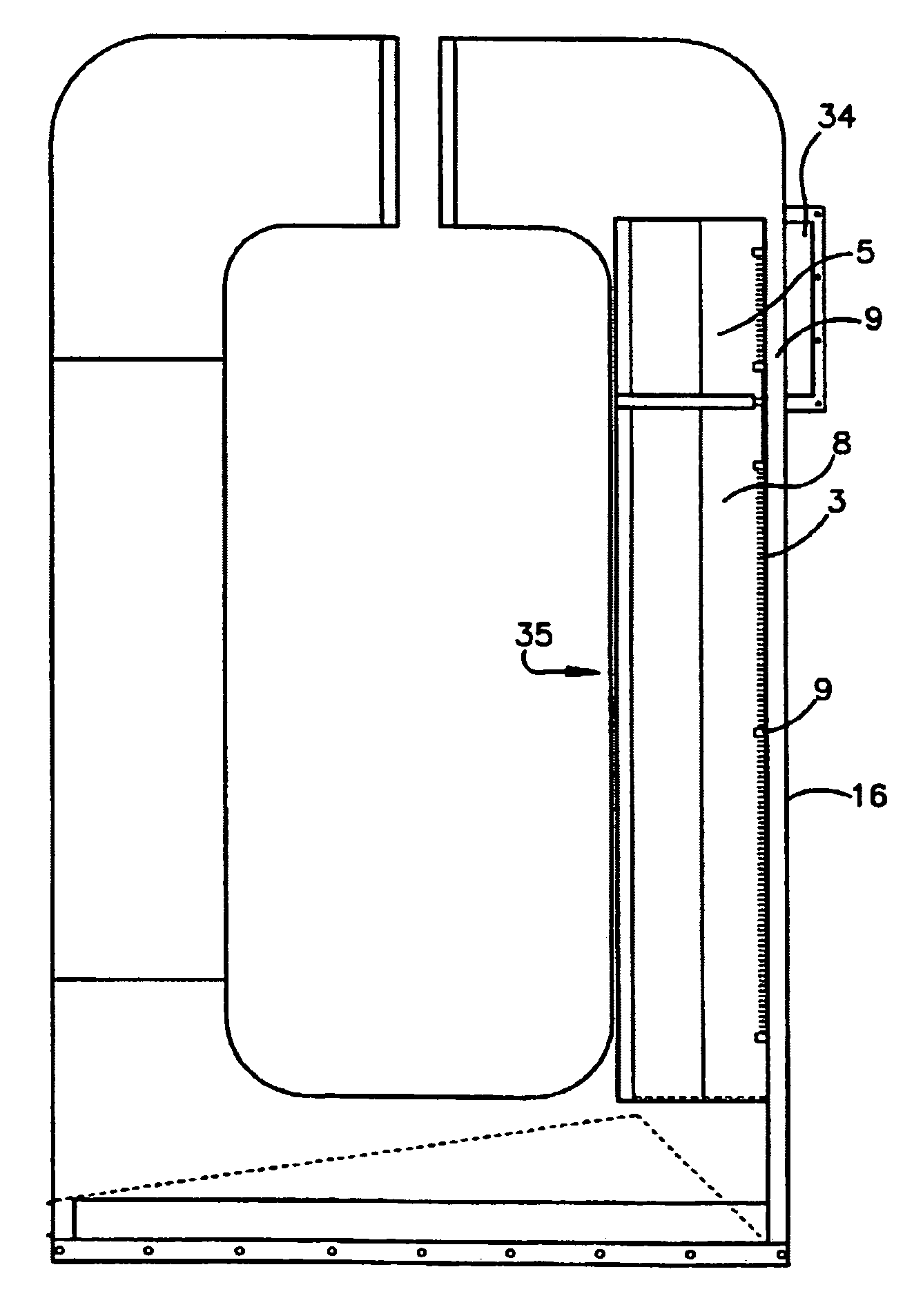
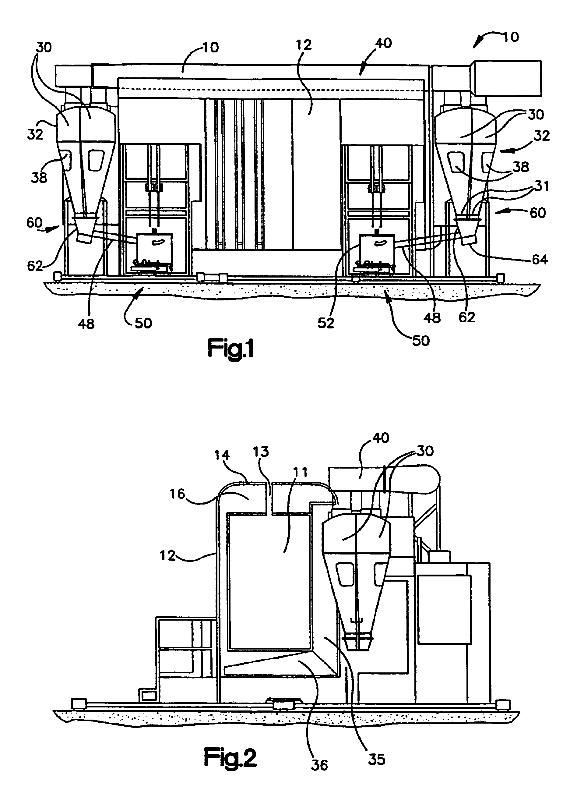
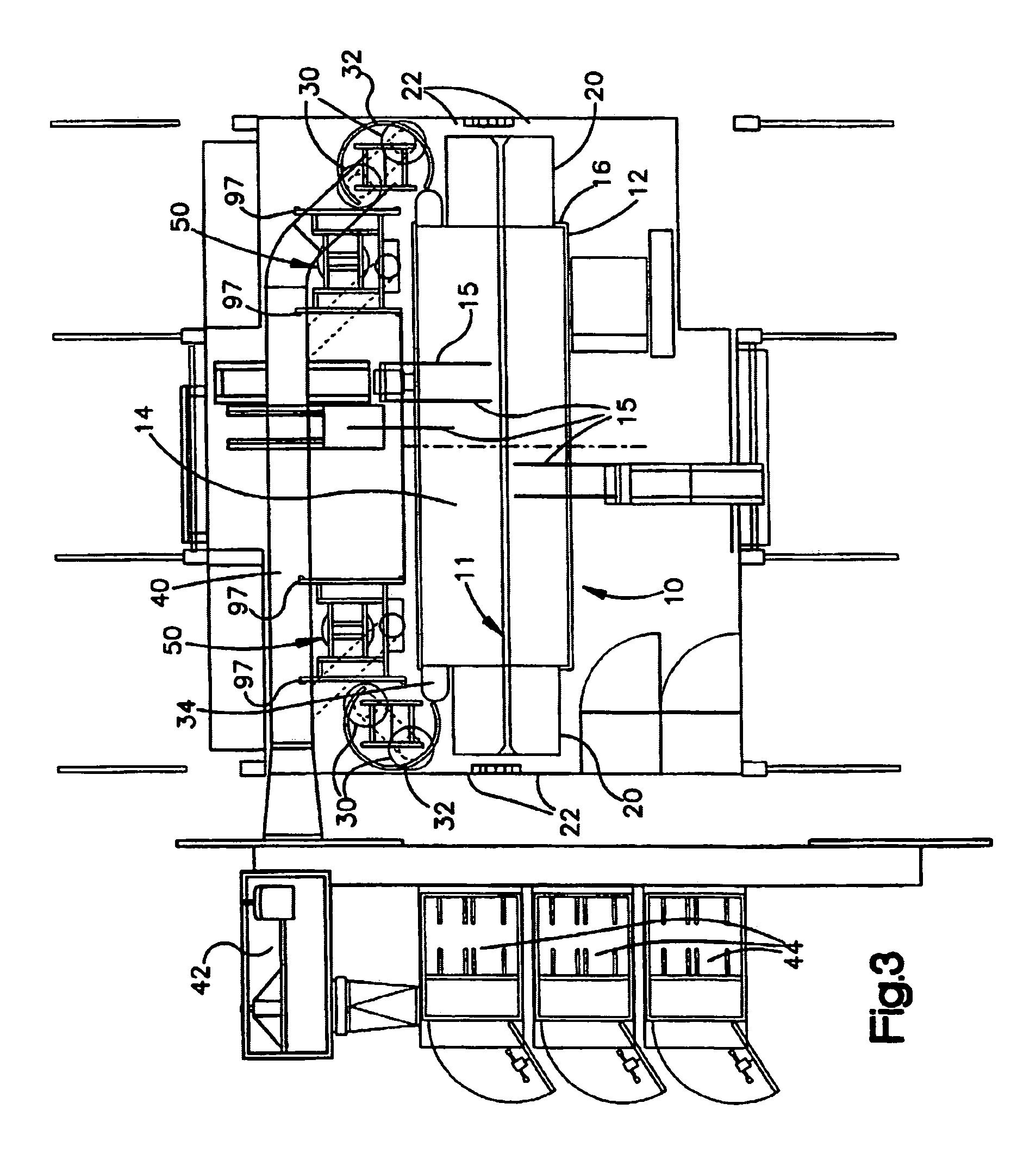
[0052]Referring now to FIGS. 1–3, a powder coating spray booth 10 is shown. The powder coating spray booth is typically substantially rectangular and the upper part or canopy of the booth which forms the walls and ceiling are made of a non-conductive material such as plastic. Since the powder coating materials are typically applied by electrostatic application devices and are charged thereby, the non-conductive booth wall and ceiling materials prevent the majority of over-sprayed coating materials from adhering to the booth walls and ceiling, thereby facilitating cleaning between color changes. Interface regions for booth interior adjacent connecting surfaces are often radiused to facilitate cleaning and prevent powder coating materials from sticking or becoming entrapped in sharp angled areas. Alternative booth materials include stainless steel. Combinations of such materials may be preferable for booth construction. For example, constructing the booth canopy, which consists of sid...


PUM


Abstract

Systems and methods for applying powder coating materials in electrostatic spray systems are provided. For example, a gravity feed of recovered powder coating from the recovery system to the feed system is disclosed. In addition, a powder feed system is disclosed wherein a powder suction lance assembly has only two operable positions, a first for feeding powder from a fluidized hopper and also corresponding to a purge position for a novel purge manifold, and a second retracted position for powder color changes and servicing. Also, a pump assembly block in physical communication with an air line attachment plate, a suction tube plate, and a hose manifold is disclosed. A plurality of attachment members removably attach the air attachment plate, a suction tube plate, and the hose manifold plate to the pump assembly block. Method for applying a first powder color and a second powder color in a powder feed center are also provided. The one method includes, among other things, the step of replacing a first pump assembly and with a second pump assembly that is in fluid communication with the one or more spray devices. The second pump assembly may be a new, previously cleaned, or color dedicated pump assembly. So configured, the present invention reduces the amount of time required for a powder color change in an electrostatic spray system and reduces color cross-contamination effects involved when changing between powder colors. Powder contacting surfaces are reduced, as well.

Description

RELATED APPLICATIONS[0001]This application claims priority to U.S. Provisional Application No. 60 / 154,624, filed Sep. 17, 1999, the entire disclosure of which is hereby incorporated by reference herein.FIELD OF THE INVENTION[0002]The invention relates generally to powder coating spray systems, and more particularly, to methods and systems for facilitating the change of powder paints and coatings in such spray systems, including improved methods and apparatuses for the recovery and re-use of over-sprayed powder coatings in a spray booth, for feeding powder coatings to be sprayed, and for purging powder coatings from system components.BACKGROUND OF THE INVENTION[0003]Powder coating spray systems are used to apply powder paints and coatings to a variety of products including, for example, appliances automotive components, furniture and storage shelving, electrical transformers, and recreational equipment. These systems often apply the coating materials to such products electrostaticall...

Claims


Application Information

Patent Timeline
IPC IPC(8): B05B15/12B05C19/00B05B15/04B05B7/14B05B12/14
CPCB05B7/1454B05B7/1472B05B12/14B05B15/1285B05B15/1288B05B15/1229Y10S55/46B05B14/48B05B16/90B05B14/45Y02P70/10
Inventor SHUTIC, JEFFREY R.JONES, EDWARD L.THOMAS, MICHAEL S.PEDDIE, ANDREW M.KREEGER, KENNETH A.SCHROEDER, JOSEPH G.
Owner NORDSON CORP
Why Eureka
Try Eureka