
Multistage hemodiafiltration/hemofiltration method and apparatus

a hemodiafiltration and multi-stage technology, applied in the direction of moving filter element filters, filtration separation, separation processes, etc., can solve the problems of reducing the removal of small molecules, urea and creatinine, and the amount of fluid that may be filtered from the blood as it passes through the dialyzer cartridge,

Inactive Publication Date: 2006-07-11
LAMBDA INVESTORS
View PDF8 Cites 94 Cited by
  • Summary
  • Abstract
  • Description
  • Claims
  • Application Information

AI Technical Summary

Benefits of technology

[0007]It is an object to provide a hemodiafiltration / hemofiltration method and apparatus that overcome the convection limitation associated with on-line post-dilution hemodiafiltration schemes using a single dialyzer cartridge, as well as the loss of small molecule clearance associated with on-line pre-dilution hemodiafiltration schemes using a single dialyzer cartridge.
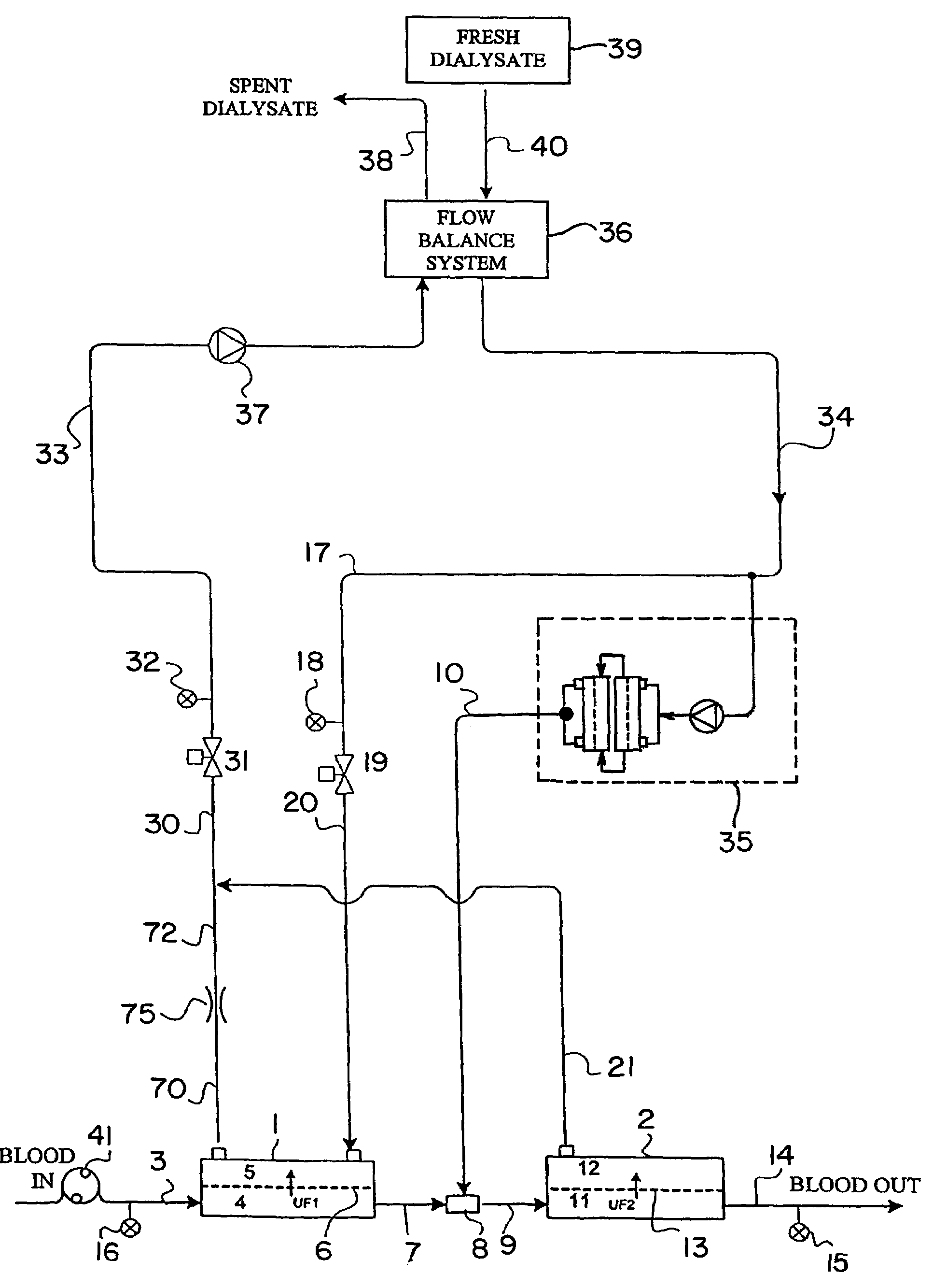
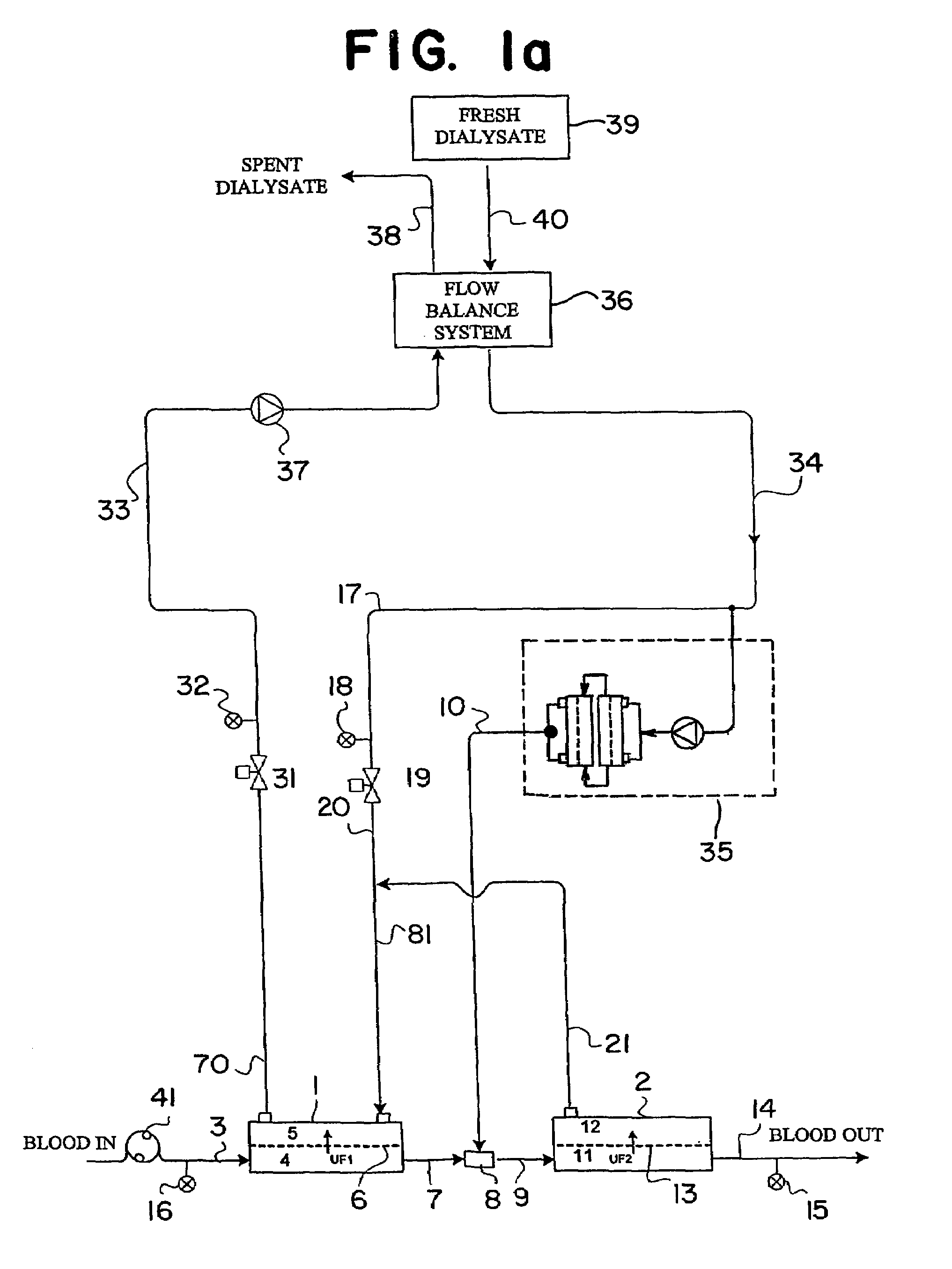
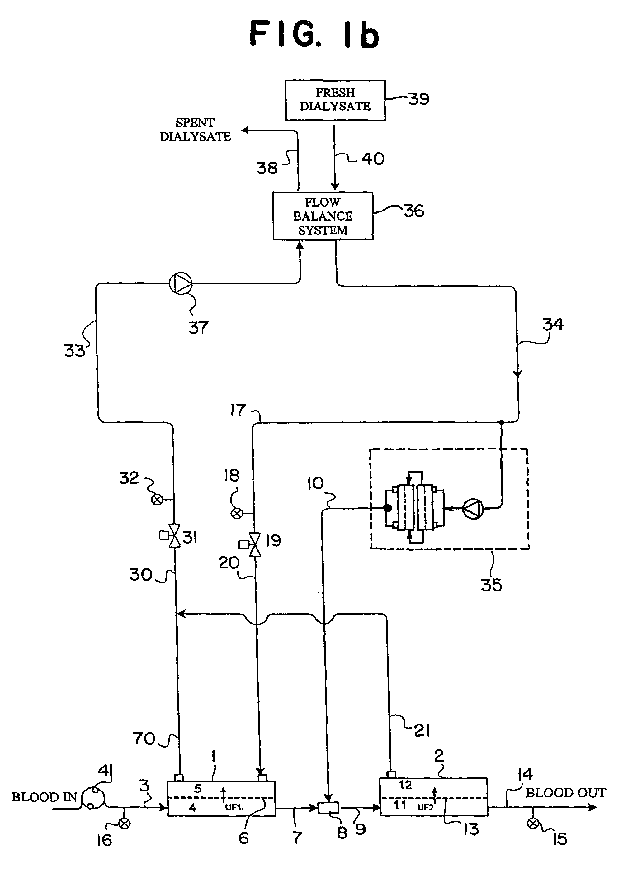
[0011]During operation of the system, blood enters the bloodside compartment of the first dialyzer cartridge, wherein a portion of plasma water is filtered across the semi-permeable membrane into the adjacent dialysate compartment. Upon exiting the first dialyzer cartridge, substitution fluid is added back to the blood at a rate higher than the rate at which fluid is filtered out of the blood in the first dialyzer cartridge. The diluted blood then enters the bloodside compartment of the second hemofilter cartridge, wherein additional plasma water is filtered across the semi-permeable membrane into the adjacent permeate compartment at a rate substantially equal to the difference between the rate at which substitution fluid is added to the blood upon exiting the first dialyzer cartridge and the filtration rate at the first dialyzer cartridge. Thus, the substitution fluid acts as a post-dilution fluid relative to the first dialyzer cartridge as well as a pre-dilution fluid relative to the second hemofilter cartridge. The advantage of operating the system in this mode is the improved clearance of larger molecular weight substances because the total filtration of plasma water can be effectively increased (e.g., 40% to 100% of the incoming blood flow rate) compared to that of a single dialyzer cartridge operating in a post-dilution mode or two dialyzers in series with the second dialyzer being operated in a reverse-filtration mode.

Problems solved by technology

For example, on-line pre-dilution hemodiafiltration schemes generally achieve higher convection filtration rates, compared to on-line post-dilution hemodiafiltration, enhancing removal of large molecules; however, the increased removal by convection comes at the expense of reducing the removal of small molecules, such as urea and creatinine.
In on-line post-dilution hemodiafiltration schemes, on the other hand, the amount of fluid that may be filtered from the blood as it passes through the dialyzer cartridge is limited.

Method used


Image

  • Multistage hemodiafiltration/hemofiltration method and apparatus
  • Multistage hemodiafiltration/hemofiltration method and apparatus
  • Multistage hemodiafiltration/hemofiltration method and apparatus

Examples


Embodiment Construction

[0029]In the embodiment of FIG. 1a, blood to be cleaned 3 is pumped by a blood pump 41 and enters a first dialyzer cartridge 1. As shown in FIG. 1a, inlet blood circuit pressure 16 (denoted “Pa”) is measured upon exiting blood pump 41, to be used as a monitoring and control parameter of the blood flow prior to entering the first dialyzer cartridge 1. The blood carrying tubing may be any suitable bloodline tubing known in the art, for example a flexible polyvinylchloride (PVC) tubing. The blood flow rate is generally in the range of about 200 to about 700 ml / min, preferably about 300 to about 600 ml / min.

[0030]Dialyzer cartridge 1 contains a semi-permeable membrane 6 that divides the dialyzer into a blood compartment 4 and a dialysate compartment 5. As blood passes through the blood compartment, plasma water containing blood substances is filtered across the semi-permeable membrane 6 (denoted “UF1” in FIG. 1a). Additional blood substances are transferred across the semi-permeable memb...


PUM

PropertyMeasurementUnit
Lengthaaaaaaaaaa
Pressureaaaaaaaaaa
Flow rateaaaaaaaaaa

Abstract

In a blood dialysis system including a source of substitution fluid (10) and a blood dialysis machine, a hemodiafiltration system having a first dialyzer (1) including a first blood compartment (4) having a first blood inlet which receives blood to be cleaned and a first blood outlet which discharges partially diafiltered blood and a first dialysate compartment (5) having a first dialysate inlet and a first dialysate outlet, means (8) for mixing the partially diafiltered blood with substitution fluid from the source to obtain a blood / substitution fluid mixture, and a second hemofilter (2) including a second blood compartment (11) having a second blood inlet which receives the blood / substitution fluid mixture and a second blood outlet which discharges filtered blood and a second permeate compartment (12) having a second permeate outlet.

Description

CROSS REFERENCE TO RELATED APPLICATION[0001]This is a U.S. national phase application under 35 U.S.C. §371 of International patent application serial No. PCT / US01 / 50503, filed Dec. 20, 2001 and claims the benefit of U.S. provisional application Ser. No. 60 / 257,191, filed Dec. 20, 2000, which is hereby incorporated by reference in its entirety. The International Application was published in English on Jun. 27, 2002 as WO 02 / 049745 A1 under PCT Article 21(2).TECHNICAL FIELD[0002]The invention relates to blood cleansing systems in general and, more particularly, to a blood cleansing modality including a hemodiafiltration stage as well as a hemofiltration stage.BACKGROUND OF THE INVENTION[0003]Hemodiafiltration combines both standard hemodialysis and hemofiltration into one process, whereby a dialyzer cartridge containing a high flux membrane is used to remove substances from the blood both by diffusion and by convection. The removal of substances by diffusion is accomplished by establi...

Claims


Application Information

Patent Timeline
IPC IPC(8): B01D61/24B01D61/28B01D61/32B01D63/00B01D61/00A61M1/14A61M1/00A61M1/34B01D61/58
CPCA61M1/3413A61M1/342A61M1/3434B01D61/58A61M1/3417B01D61/243B01D61/145Y10S210/929A61M1/3441A61M1/3437A61M1/3465A61M1/3401B01D61/244
Inventor SUMMERTON, JAMESCOLLINS, GREGORY R.SPENCE, EDWARD
Owner LAMBDA INVESTORS
Learn More