Composite material-stiffened panel and manufacturing method thereof

a technology of stiffening panel and composite material, which is applied in the direction of transportation and packaging, other domestic articles, efficient propulsion technologies, etc., can solve the problems of high cost, reduced fatigue strength due to stress concentration of fastener-hole, and high cost, and achieves enhanced bonding

Inactive Publication Date: 2006-07-11
SUBARU CORP
View PDF7 Cites 130 Cited by
  • Summary
  • Abstract
  • Description
  • Claims
  • Application Information

AI Technical Summary

Benefits of technology

[0014]In view of the problems discussed above, an object of the present invention is to provide a composite material-stiffened panel for enhanced bonding of a fiber-reinforced resin-composite skin and a stiffener and a manufacturing method thereof.

Problems solved by technology

The method of manufacturing a stiffened panel by binding a skin and a stiffener by means of a fastener requires molding of the skin and the stiffener and provision of a positioning tool, thus resulting in high cost.
Other problems are strict fastener design requirements (hole-edge distance and skin thickness for no sharp edges to a countersink) and reducing of fatigue strength due to a fastener-hole stress concentration.
The method of manufacturing a stiffened panel by bonding a skin and a stiffener by means of an adhesive requires molding of the skin and the stiffener, a pre-bonding process for the skin and the stiffener, positioning the skin and the stiffener, and provision of a pressurized holding tool for bonding, thus the cost becomes high.
The method of manufacturing a stiffened panel by machining a thick metal plate by machine working has a problem that since much of the material is cut and discarded, resources are wasted, and a problem that as weight efficiency is heightened, the cost of machine working becomes higher.
The method of manufacturing a stiffened panel by means of integral molding of a composite material has a problem of high cost factors such as provision of a complex tool for an accurately and integrally molded shape and of pressurizing the entire surface and an increase in scrap risk.

Method used


Image

  • Composite material-stiffened panel and manufacturing method thereof
  • Composite material-stiffened panel and manufacturing method thereof
  • Composite material-stiffened panel and manufacturing method thereof

Examples


Embodiment Construction

[0027]Preferred embodiments according to the present invention will be disclosed with reference to the attached drawings.

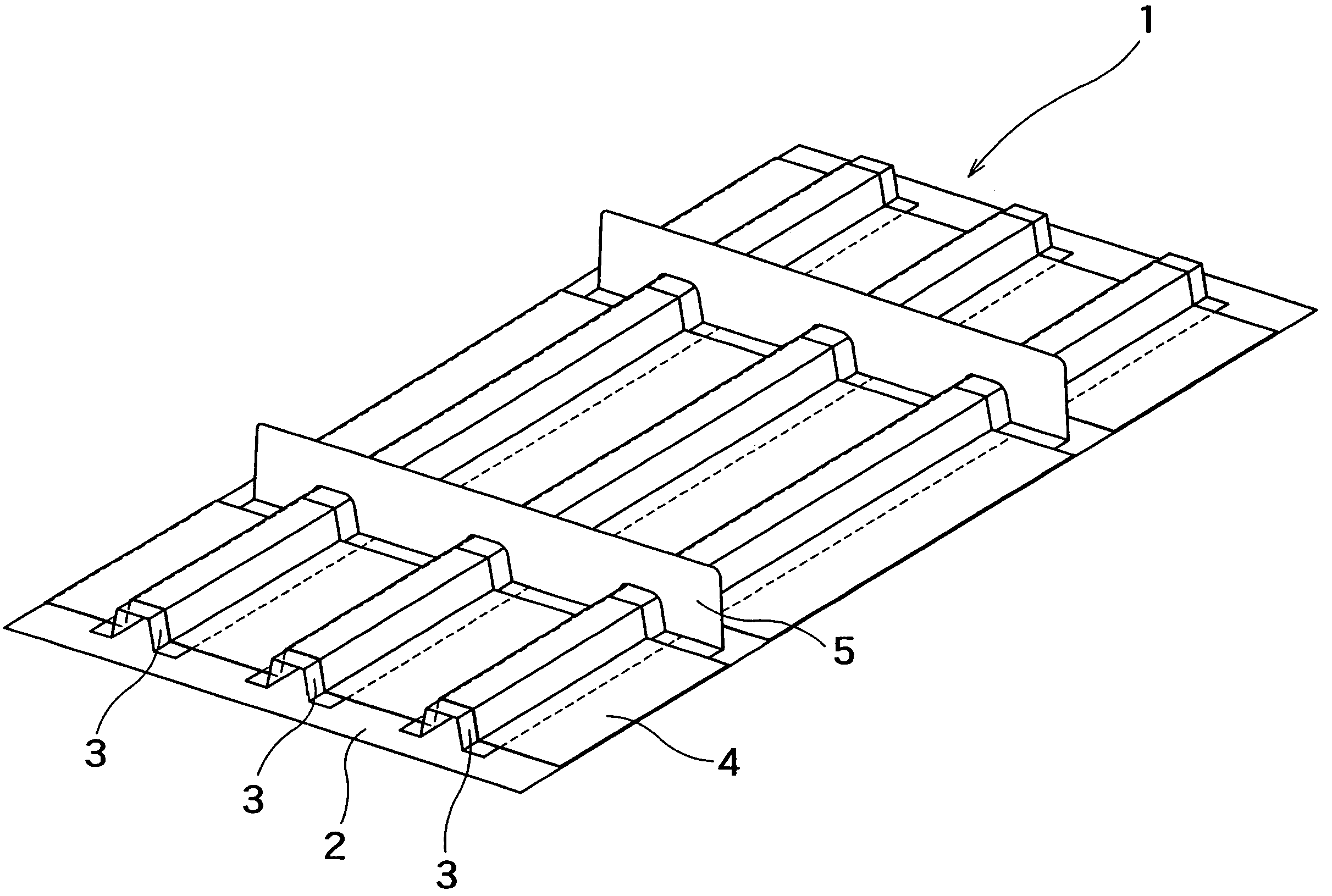
[0028]In FIG. 5, a composite material-stiffened panel 1 is applied to an aircraft wing and tail-assembly to be a fuel tank.

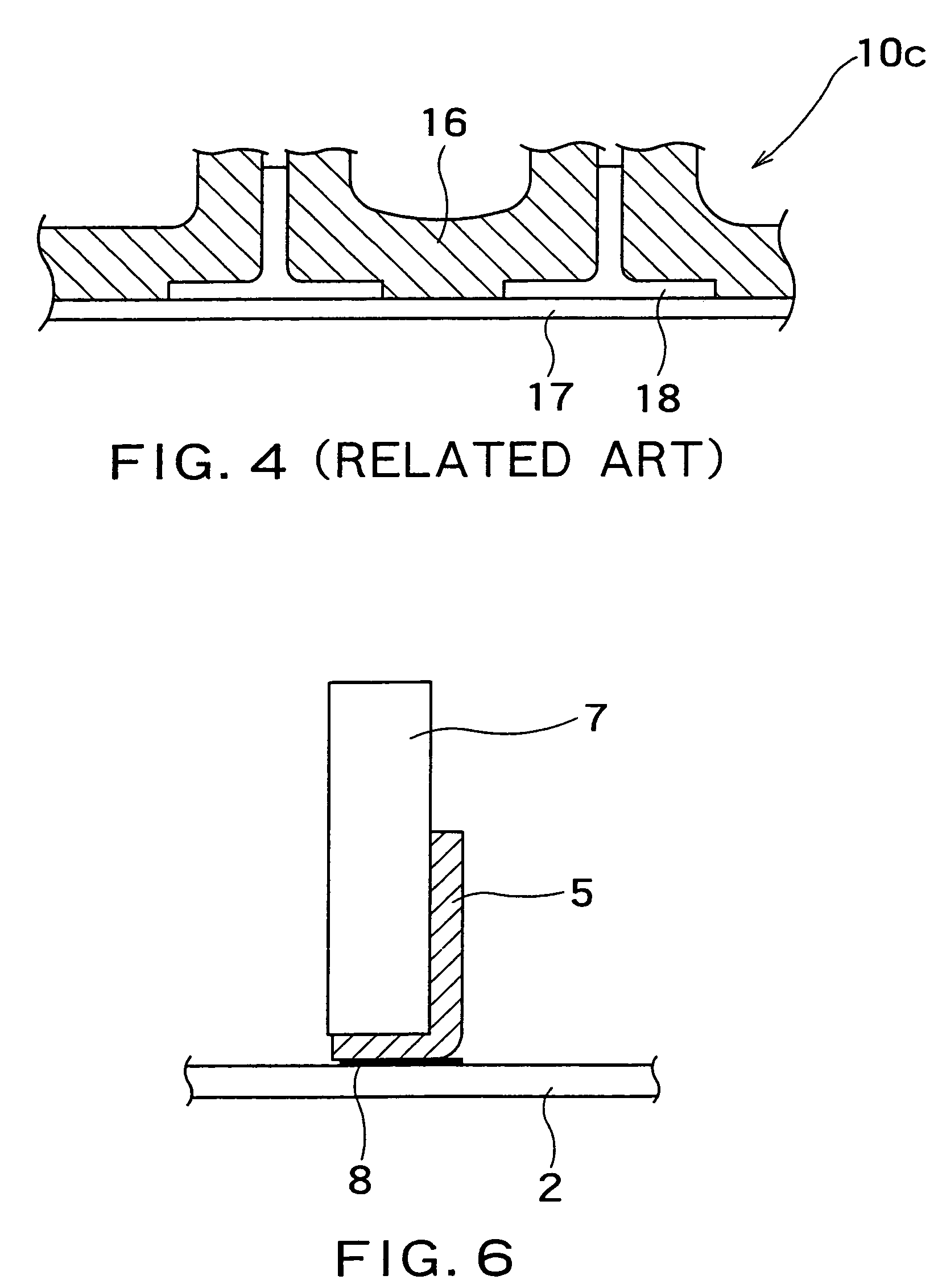
[0029]The composite material-stiffened panel 1 has a skin 2, several stiffeners 3, a fiber-reinforced resin-composite material 4 and ribs 5. The skin 2 is obtained by molding a fiber-reinforced resin-composite material into a flat skin. The stiffeners 3 are arranged in rows on one surface of the skin 2 with a gap in one direction. The fiber-reinforced resin-composite material 4 is provided on and stitched on the skin 2 so as to partially cover the stiffeners 3. The ribs 5 connect the stiffeners 3 each arranged in rows.

[0030]It is preferable that the fiber of the fiber-reinforced resin-composite material 2 is composed of a composite-material-dry preform of three-dimensional fabric where warp, weft and vertical yarn are combined three-dimensiona...


PUM

PropertyMeasurementUnit
shapeaaaaaaaaaa
shapesaaaaaaaaaa
skin thicknessaaaaaaaaaa

Abstract

A composite material-stiffened panel has a skin obtained by molding a fiber-reinforced resin composite material into a flat skin, stiffeners arranged in rows on one surface of the skin, and a fiber-reinforced resin-composite material stitched on the skin covering the stiffeners. The composite material-stiffened panel can be manufactured as follows: A first fabric material is placed on a tool having a panel-shaped surface. Stiffeners are placed on the first fabric materials. A second fabric material is placed on the stiffeners to cover at least some of the stiffeners. The second fabric materials are reformed to match the shape of the stiffeners. The reformed second fabric material is stitched on the first fabric material along edges of the stiffeners. All the materials are covered with a bagging film for vacuum. Resin is infiltrated into the fabric materials by a RTM or a RFI method. The infiltrated resin is heated to be hardened.

Description

CROSS REFERENCE TO RELATED APPLICATION[0001]This application is a division of Ser. No. 10 / 023,725, filed Dec. 21, 2001, now U.S. Pat. No. 6,702,911. which is incorporated herein by reference in its entirety.BACKGROUND OF THE INVENTION[0002]1. Field of the Invention[0003]The present invention relates to a composite material-stiffened panel to be applied to a wing and a tail assembly of an aircraft and a manufacturing method thereof.[0004]2. Description of the Related Art[0005]As a conventional stiffened panel, stiffened panels shown in FIGS. 1 through 4 are known.[0006]A stiffened panel 10 shown in FIG. 1 is formed in such a manner that a skin 11 and a stiffener 12 are manufactured according to respective shapes, and they are bound to each other by a fastener 13 (rivet or the like).[0007]A stiffened panel 10a shown in FIG. 2 is formed in such a manner that a skin 11a and a stiffener 12a are manufactured according to respective shapes, and they are bonded by an adhesive 14.[0008]A sti...

Claims


Application Information

Patent Timeline
Patent Type & Authority Patents(United States)
IPC IPC(8): B32B3/06B29C43/12B64C3/26B29C70/06B29C70/44B29D99/00B32B3/10B32B5/02B32B5/06B64C3/20
CPCB29C70/443B64C1/12B29C43/12Y10T428/24033Y10T428/24174Y10T428/24198Y10T428/24661Y02T50/433Y02T50/40
Inventor TOI, YASUHIRONODA, MASAHIROHARADA, ATSUSHITANAKA, SHIGEKI
Owner SUBARU CORP
Why Eureka
Try Eureka