High power radiation emitter device and heat dissipating package for electronic components

a radiation emitter and heat dissipation package technology, applied in the direction of instruments, lenses, optical elements, etc., can solve the problems of reducing the emission efficiency of leds, increasing the probability of failure in most conditions, and affecting the efficiency and reliability of leds. normal, the effect of high power density, high radiant flux and/or luminous flux emission

Inactive Publication Date: 2006-07-11
GENTEX CORP
View PDF47 Cites 75 Cited by
  • Summary
  • Abstract
  • Description
  • Claims
  • Application Information

AI Technical Summary

Benefits of technology

[0021]It is an aspect of the present invention to provide a relatively high power and high power density radiation emitter device capable of high radiant flux and / or luminous flux emission. It is a further aspect of the present invention to provide a radiation emitter device exhibiting relatively low temperature rise due to internal power dissipation and increased reliability by virtue of relatively low thermal resistance. To achieve these and other aspects and advantages in accordance with one embodiment of the present invention, the radiation emitting device of the present invention comprises a sealed chamber; one or more liquids or gels contained in the sealed chamber; an electroluminescent emitter that emits optical radiation in response to an electrical signal, the electroluminescent emitter is disposed in the sealed chamber in physical and thermal contact with one of the liquids or gels; and first and second electrical conductors electrically coupled to the electroluminescent emitter for energizing the electroluminescent emitter. A portion of the structure defining the sealed chamber may be partially transparent to allow the radiation to enter or exit.

Problems solved by technology

Elevated operating temperatures simultaneously reduce the emission efficiency of LEDs and increase the probability of failure in most conditions.
Regardless of the cause, LED efficiency and reliability are normal adversely affected by increases in temperature.
To limit the operational temperature of the LED, the power that is allowed to be dissipated through the LED is typically limited.
To limit the dissipated power, however, the current that may be passed through the LED must be limited, which in turn limits the emitted flux of the LED since the emitted flux is typically proportional to the electrical current passed through the LED.
An increase in LED chip temperature results in a corresponding decrease in their emission efficiency.
Most prior art devices, however, exhibit relatively high thermal resistance from their semiconductor radiation emitter to ambient and are compelled to limit power dissipation in order to avoid internal damage.
Thus, the best 5 mm T-1¾ THD packages are limited to about 110 mW continuous power dissipation at 25° C. ambient temperature.
An additional problem faced by designers of conventional LED devices is that the wire bond used to join one of the LED leads to the LED chip can break or lose contact with the lead or the chip.
Such failure can occur, for example, due to shear forces that are transferred to the wire bond through the encapsulant or thermal expansion / contraction of the encapsulant around the wire bond.
The other forms of radiation emitters mentioned above also experience performance degradation, damage, increased failure probability or accelerated decay if exposed to excessive operating temperatures.
Similar heat dissipation problems exist with respect to other electronic components.

Method used


Image

  • High power radiation emitter device and heat dissipating package for electronic components
  • High power radiation emitter device and heat dissipating package for electronic components
  • High power radiation emitter device and heat dissipating package for electronic components

Examples


example

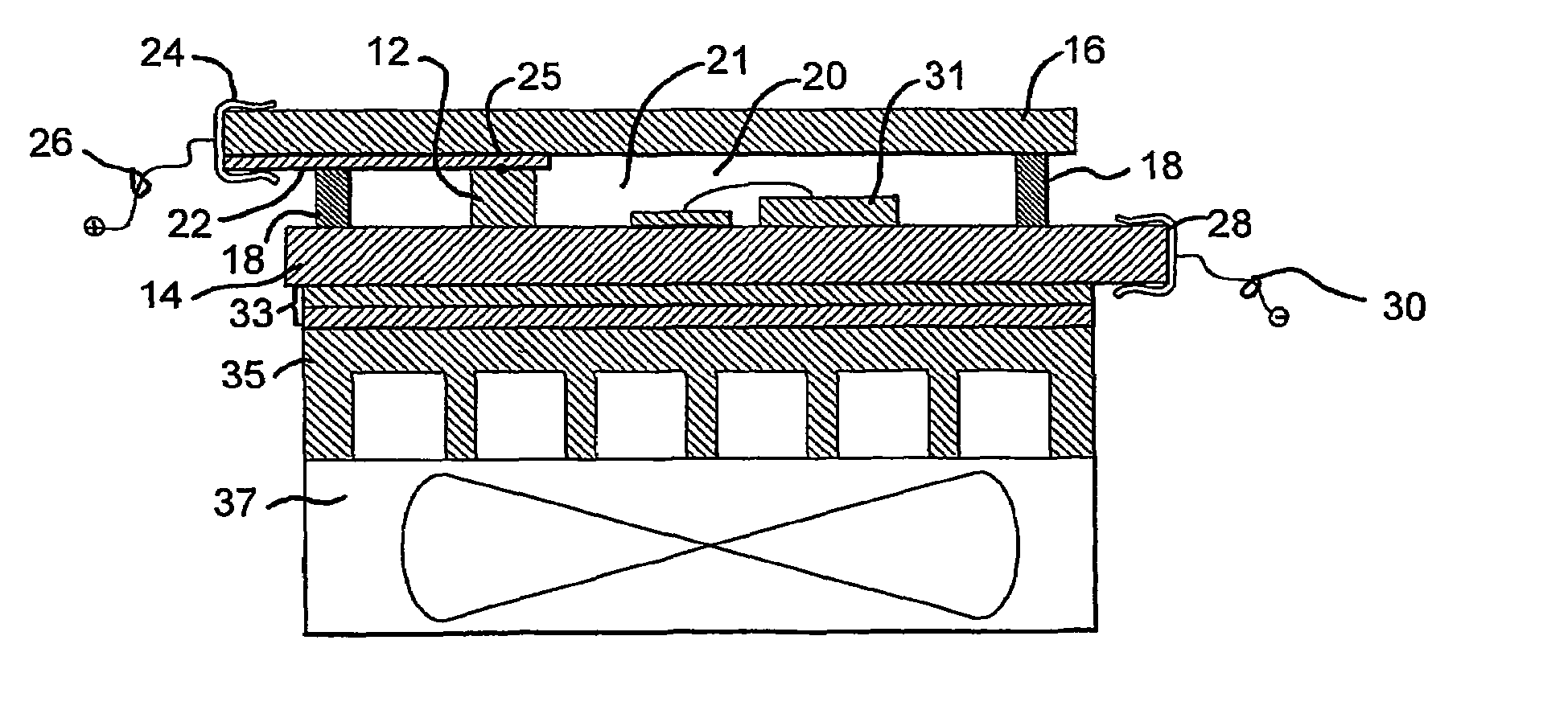
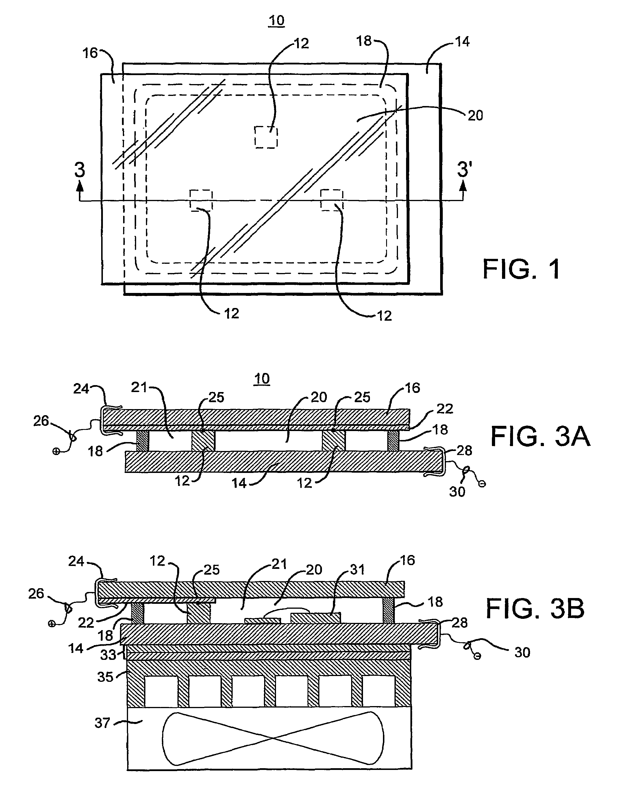
[0099]To demonstrate the effectiveness of the present invention, a package assembly was constructed as illustrated in FIGS. 10 and 11 and described above. The structure had a length of approximately 1.5 inches and a width of approximately 1.5 inches, with the external contact pads being approximately 0.25 inch long. To demonstrate the effectiveness of the present invention, the illumination from the device was measured at various power levels prior to filling the sealed chamber 21 with any liquid. Then, the assembly was filled with liquid and plugged and the illuminance was again measured at the same power levels. The results of these measurements are illustrated in FIG. 12, with the illuminance measured in foot-candles at 18 inches. As apparent from FIG. 12, the provision of the liquid in physical and thermal contact with the LEDs improved their performance markedly. The improvement increased as the applied power increased. It should be understood that, for this sample, increased i...


PUM


Abstract

The electronic component package (10) of the present invention includes a sealed chamber; a liquid or gel (20) contained in the sealed chamber; at least one electronic component (12) disposed in the sealed chamber in physical and thermal contact with the liquid or gel (20); and at least one electrical conductor electrically coupled to the electronic component and extending out of the sealed chamber. The electronic component(s) (12) may include any one or combination of a radiation emitter, a thermal or optical sensor, a resistor, and a microprocessor or other semiconductor component.

Description

CROSS-REFERENCE TO RELATED APPLICATIONS[0001]This application is a continuation-in-part of U.S. patent application Ser. No. 09 / 835,238 filed on Apr. 13, 2001, now U.S. Pat. No. 6,639,360, which claims benefit of U.S. Provisional Application No. 60 / 265,487 filed on Jan. 31, 2001.BACKGROUND OF THE INVENTION[0002]The present invention generally relates to radiation emitter assemblies such as, for example, light emitting diode (LED) packages and to heat dissipating packages for electronic components.[0003]Radiation emitters, particularly optical radiation emitters, are used in a wide variety of commercial and industrial products and systems and accordingly come in many forms and packages. As used herein, the term “optical radiation emitter” includes all emitter devices that emit visible light, near infrared (IR) radiation, and ultraviolet (UV) radiation. Such optical radiation emitters may be photoluminescent, electroluminescent, or other solid state emitter. Photoluminescent sources in...

Claims


Application Information

Patent Timeline
Patent Type & Authority Patents(United States)
IPC IPC(8): H01L27/15H01L31/12H01L33/00H01L23/42H01L33/64H05B33/04
CPCG02B3/0056H01L33/648H05B33/04H01L23/42H01L2224/48091H01L2924/00014
Inventor ROBERTS, JOHN K.REESE, SPENCER D.
Owner GENTEX CORP
Why Eureka
Try Eureka