Overcurrent protection circuit with fast current limiting control

a current limit and circuit technology, applied in the direction of gain control, single-ended push-pull amplifiers, pulse techniques, etc., can solve the problems of physical damage to the power transistor output device undesired system issues

Inactive Publication Date: 2006-07-11
MICREL
View PDF8 Cites 36 Cited by
  • Summary
  • Abstract
  • Description
  • Claims
  • Application Information

AI Technical Summary

Problems solved by technology

In the extreme case of an “abrupt short circuit” or “crowbar short circuit,” a slow detection and protection response may allow excessive current to flow for extended period of time, causing physical damage to the power transistor output device.
Furthermore, slow detection and protection response to an overcurrent event can introduces undesired system issues.
If the load current becomes excessive and current limiting response is not activated fast enough, the supply voltage may dip, causing undesired system issues.
A slow overcurrent detection and protection response will thus result in frequent system resets which are undesirable.
Furthermore, the integrated circuit's status register may not indicate an overcurrent fault since the integrated circuit was reset due to the undervoltage condition of the supply voltage.
In a power transistor, the slow detection and protection response to an abrupt short circuit condition is usually due to the large gate capacitance (up to 500 pf) of the power transistor and the limited current supplied to the driver circuit driving the power transistor.

Method used


Image

  • Overcurrent protection circuit with fast current limiting control
  • Overcurrent protection circuit with fast current limiting control
  • Overcurrent protection circuit with fast current limiting control

Examples


Embodiment Construction

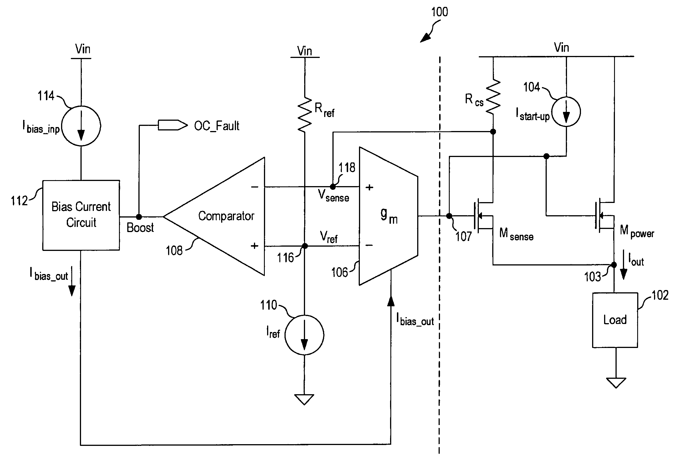
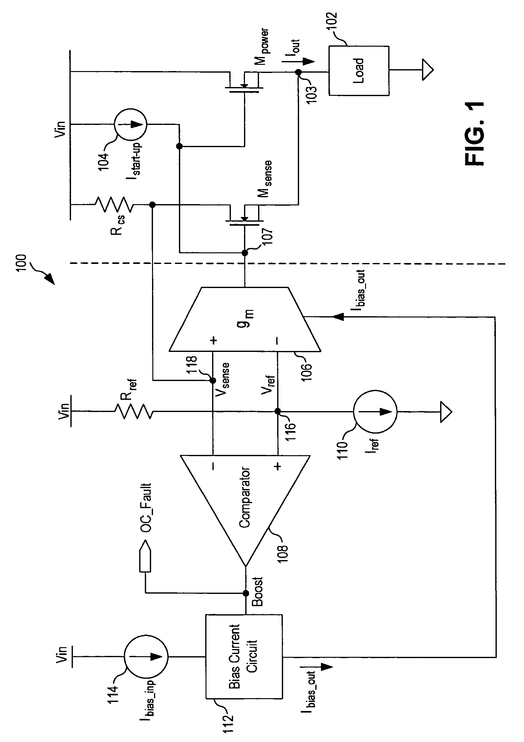
[0017]In accordance with the principles of the present invention, an overcurrent protection circuit for a power transistor includes a comparator for detecting and indicating an overcurrent condition and a bias current circuit for providing a boost current to a driver circuit driving the power transistor in response to the overcurrent condition. The driver circuit, receiving the boost current, provides fast response in limiting the output current of the power transistor. The overcurrent protection circuit of the present invention operates to provide very fast current limiting response so that damages to the power transistor and undesired system resets are prevented. In general, the overcurrent protection circuit can be applied to any power controlling pass device for providing overcurrent protection where fast current limiting response is critical. The overcurrent protection circuit of the present invention has the advantages of low power consumption and simplified circuitry and thus...


PUM


Abstract

An overcurrent protection circuit for a power transistor includes a transconductance amplifier and a bias current circuit. The transconductance amplifier receives a first signal indicative of the magnitude of the load current conducted by the power transistor and a reference voltage and provides a second signal for controlling the load current. The transconductance amplifier further provides a third signal having a first logical state indicating normal operation and a second logical state indicating an overcurrent condition at the power transistor. The bias current circuit provides an output bias current to the transconductance amplifier in response to the third signal where the output bias current has a nominal current value in normal operation and an increased current value in an overcurrent condition. In this manner, a boost current is provided to the transconductance amplifier to increase the current limit response time when an overcurrent condition is detected.

Description

FIELD OF THE INVENTION[0001]The invention relates to a circuit for overcurrent protection and, in particular, to a circuit for detecting overcurrent events and providing fast current limiting response to the overcurrent events, such as short circuit events.DESCRIPTION OF THE RELATED ART[0002]In integrated circuits, overcurrent protection is often included to protect the integrated circuits against excessive loads, such as short circuits at the output load, so as to prevent damage to the integrated circuits. Overcurrent protection can be implemented as a current limiting circuit or an electronic circuit breaker whereby, in response to a rapid increase in load current, the load current is either limited to a certain maximum level or the integrated circuit is shut off entirely.[0003]Overcurrent protection is essential for power transistors that are used in high voltage or high current applications to prevent damages to the power transistors caused by excessive load currents. In the ext...

Claims


Application Information

Patent Timeline
Patent Type & Authority Patents(United States)
IPC IPC(8): H03F1/52
CPCH03F1/523H03K17/0822H03K2217/0027H03K17/18
Inventor BRISKIN, BORISBURKLAND, WILLIAM A.
Owner MICREL
Why Eureka
Try Eureka