Method of servo writing for magnetic recording system, magnetic recording system

a technology of magnetic recording system and servo writing, which is applied in the direction of digital recording, maintaining head carrier alignment, instruments, etc., can solve the problems of deteriorating position signal quality, affecting the stability of the position signal, so as to improve the anti-signal decay performance, reduce the demagnetization field in the servo area, and improve the servo signal quality

Inactive Publication Date: 2006-07-11
WESTERN DIGITAL TECH INC +1
View PDF21 Cites 12 Cited by
  • Summary
  • Abstract
  • Description
  • Claims
  • Application Information

AI Technical Summary

Benefits of technology

[0019]An object of the present invention is to solve the problem described above and to provide a longitudinal magnetic recording system wherein a signal with a shorter bit length than the burst signal, i.e. a signal of a shorter wavelength than the burst signal is recorded in what conventionally has been the DC erased area of the servo area or an area having a very long wavelength recorded therein. In this way, the demagnetization field in the servo area is reduced, and the anti-signal decay performance is improved while at the same time suppressing the shift of the end of the burst signal area for an improved servo signal quality. In this invention, the DC erased area of the servo area where a signal of a shorter wavelength than the burst signal is called a dummy area.
[0020]Generally, the sensitivity of the reproduction head decreases for a recording signal of a shorter wavelength. Once the wavelength of the signal recorded in the dummy area is sufficiently shortened, therefore, the reproduction amplitude from the signal recorded in the dummy area is substantially zero and has no effect on the detection of the position signal. In some cases, the wavelength of the recorded signal recorded in the dummy area cannot be shortened sufficiently due to the performance of the servo track writer, and the reproduced output of the signal recorded in the dummy area is sometimes large to a not negligible degree. In such a case, the effect of the recorded signal in the dummy area can be removed by using a LPF (Low Pass Filter) for lowering the signal of shorter wavelength than the signal recorded in the dummy area.
[0021]The servo track writer can be controlled more easily when the signal frequency recorded in the dummy area is set to an integer multiple of the signal frequency of the servo pattern. Then, the throughput of the system production can be increased for a higher cost effectiveness.
[0022]Another object of the invention is to provide a magnetic recording system, wherein the maximum bit length of the servo area is limited and shortened to the maximum bit length of the data area or less. In perpendicular recording, the thermal demagnetization of the low density signal is so large that the thermal fluctuation occurs most conspicuously in the portion of the recorded data on the media where the recording density is lowest. The servo pattern is indispensable data for positioning the head, and the need of preventing the disappearance thereof due to the thermal fluctuation is higher than that of the user data. For this purpose, the system is designed in such a manner that the recorded bit length of the burst signal area of the servo area is set to a length at least equal to the maximum bit length of the signal recorded in the disk, and under this condition, the anti-signal decay performance is secured. By designing the servo pattern in this way, the anti-signal decay performance of the servo pattern can be secured.

Problems solved by technology

Actually, however, the tracks, which are magnetically formed, cannot be optically viewed directly.
Therefore, the reproduced waveform is distorted as shown in FIG. 22, and when integrated, a correct position signal cannot be produced due to the effect of the DC offset.
The end of the burst signal area also shifts due to a similar phenomenon, thereby deteriorating the position signal quality.
Another problem of the prior art is that the maximum bit length of the signal recorded in the servo area is longer than the maximum bit length of the data area, and under this condition, the anti-signal decay performance of the servo area is weakest from design aspect, thereby making it impossible to secure reliability.

Method used


Image

  • Method of servo writing for magnetic recording system, magnetic recording system
  • Method of servo writing for magnetic recording system, magnetic recording system
  • Method of servo writing for magnetic recording system, magnetic recording system

Examples


first embodiment

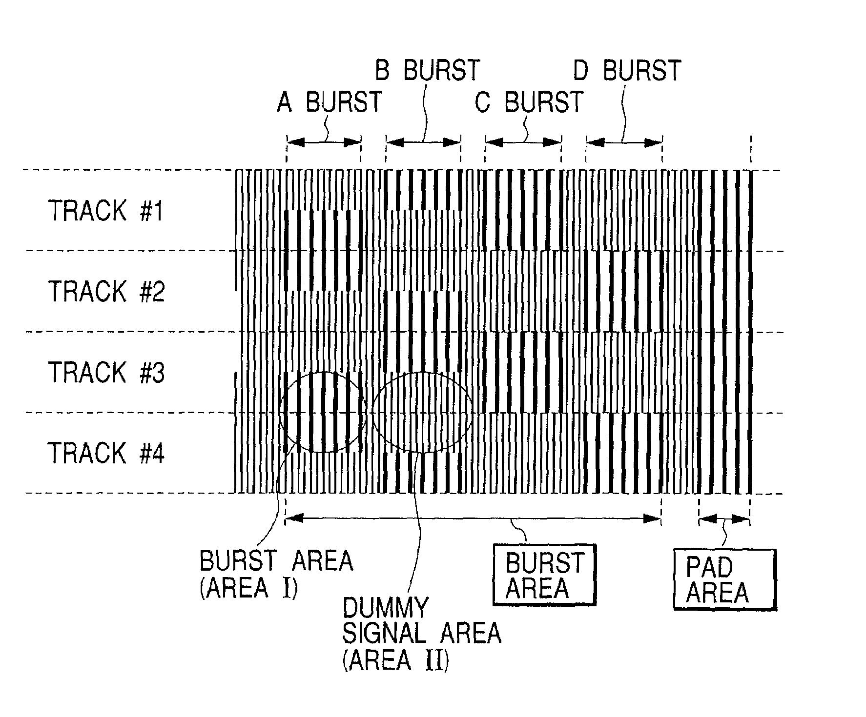
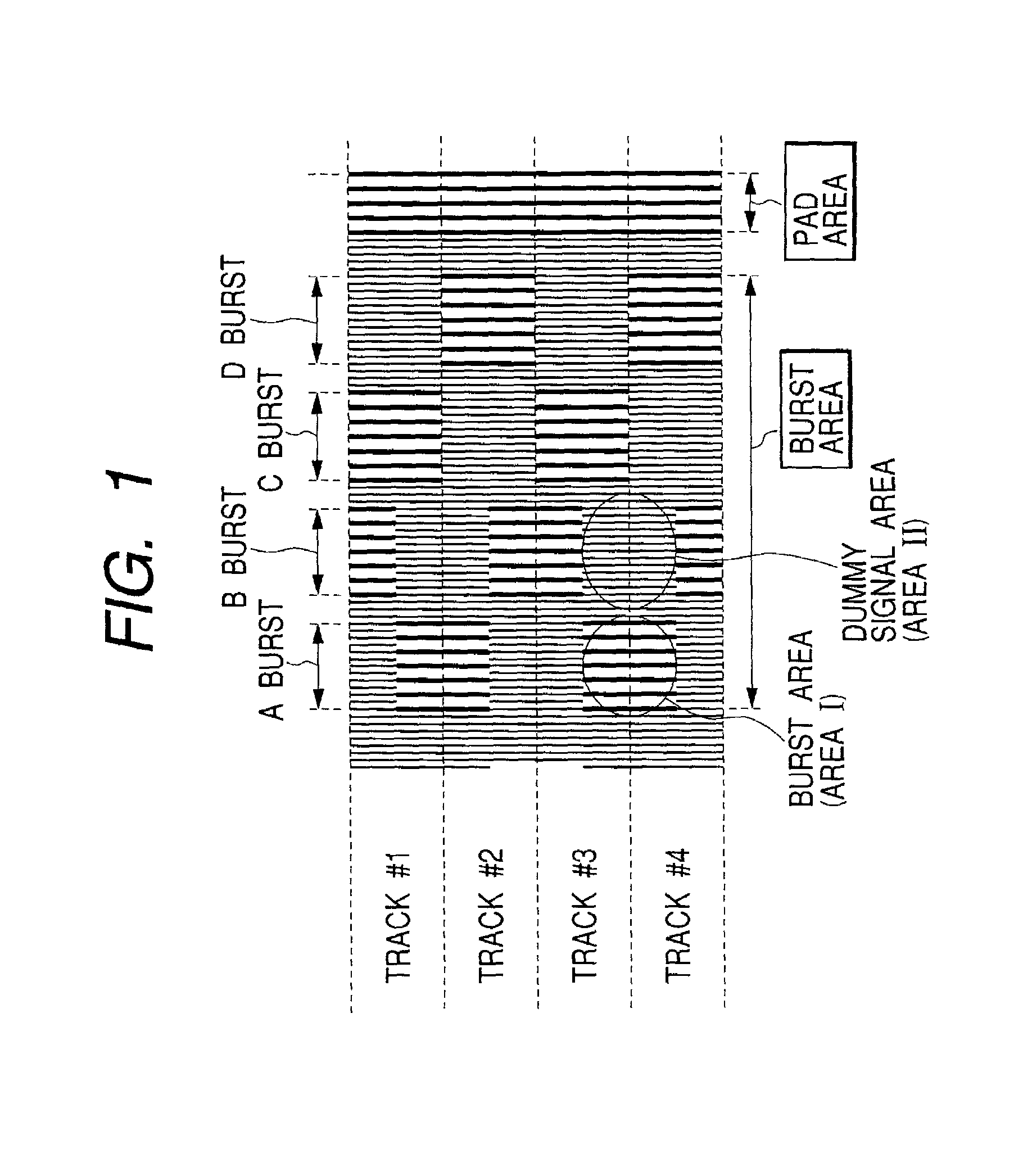
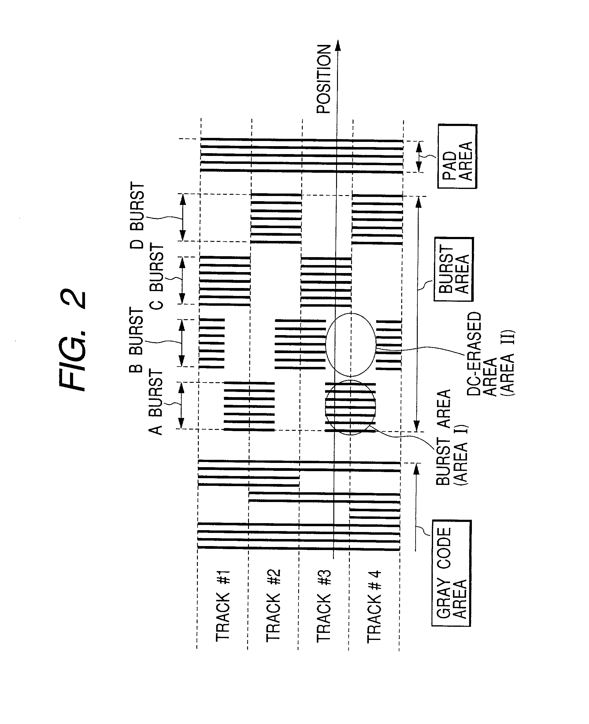
[0046]A first embodiment will be explained. According to this embodiment, there is provided a longitudinal magnetic recording system in which a pattern having a recording density twice as high as the burst signal, i.e. having a bit length one half that of the burst signal is recorded in an area which has conventionally been a DC erased area (area II in FIG. 2), i.e. a dummy area, as shown in FIG. 1.

[0047]The steps of forming the burst area with a servo writer will be explained with reference to FIGS. 3(a) to 3(e) and 4(f) to 4(i). As in the conventional longitudinal recording system, a burst pattern is formed at pitches of one half track. In what has conventionally been the DC erased area, however, a pattern having bits one half of the burst signal area is recorded. As a result, a burst pattern of hound's tooth check is formed on both sides of the dummy signal area.

[0048]FIG. 5 shows an outline of the servo system configuration. The longitudinal magnetic recording system also often ...

second embodiment

[0051]A second embodiment will be explained. According to this embodiment, the steps of forming the burst area are exactly the same as those of the first embodiment, but the servo signal processing system is different. FIG. 8 shows an outline of the processing system. Unlike the first embodiment in which the amplitude is calculated by integrating the absolute value, the present embodiment is such that the frequency component is detected (phase is detected) by use of DFT (Discrete Fourier Transform) thereby to control the position signal. The phase is detected by the frequency but not by the amplitude of the servo signal and that the frequency of the dummy area is different from that of the burst signal area. Therefore, the frequencies of the dummy area and the burst signal area can be discriminated readily. Thus, the LPF for the servo area is eliminated, and a LPF similar to that for the data area can be used.

third embodiment

[0052]A third embodiment will be explained. According to this embodiment, the steps of forming the burst area and the servo signal processing system are exactly the same as those of the second embodiment. In this embodiment, however, the recording density of the burst signal area is subjected to certain conditions. As described above, the thermal demagnetization of the low-density signal is large in perpendicular recording. That portion of the recorded data on the media which has the lowest recording density, therefore, most easily-succumbs to the thermal fluctuation. According to this embodiment, the burst signal is recorded with a bit length shorter than the maximum bit length limited by the recorded code in the data area.

[0053]This embodiment uses a code having the efficiency of 32 / 33 in which 33 recorded bits are assigned to 32 user data bits as a recorded code. With this code, the longest recorded bits are ten times as long as the shortest recorded bits. The magnetic recording ...


PUM

PropertyMeasurementUnit
widthaaaaaaaaaa
areaaaaaaaaaaa
lengthaaaaaaaaaa

Abstract

In a method of servo writing of a magnetic recording system and the magnetic recording system, the signal is recorded in a dummy area with a higher recording density than the burst signal. Also, the maximum bit length of the burst area is shortened as compared with the maximum bit length of the data area. A servo control method for perpendicular recording similar to that for longitudinal recording can be used to reduce the development cost. The anti-signal decay performance is also improved. Further, since the variations of the burst signal along the track width is suppressed, the positioning accuracy is improved. These effects combine to produce a reliable magnetic recording system of large capacity.

Description

BACKGROUND OF THE INVENTION[0001]1. Field of the Invention[0002]The present invention relates to a magnetic recording system comprising perpendicular magnetic recording media.[0003]2. Description of the Related Art[0004]The magnetic recording system is such that the head is moved radially of a rotating disk and accurately set in position on an intended data track to write and read information magnetically. A top plane view of the interior of a housing (enclosure) of a typical magnetic recording system is shown in FIG. 10, and a sectional view of the magnetic recording system is shown in FIG. 11. These diagrams illustrate a magnetic recording system configured of six heads, three disks, a rotary actuator, a voice coil motor, a head amplifier and a package board.[0005]The three disks are fixed on a single rotary shaft and driven at the rotation speed of 3000 to 15000 rpm around a point A by a spindle motor. The six heads are fixed on a single comb-shaped arm and rotationally driven ar...

Claims


Application Information

Patent Timeline
Patent Type & Authority Patents(United States)
IPC IPC(8): G11B5/09G11B5/596G11B21/10
CPCG11B5/59688G11B5/59655G11B5/596
Inventor NISHIDA, YASUTAKAHAMAGUCHI, TAKEHIKOSAWAGUCHI, HIDEKITAKANO, HISASHI
Owner WESTERN DIGITAL TECH INC
Why Eureka
Try Eureka