Power node control center

a control center and power distribution system technology, applied in the direction of process and machine control, material dimension control, instruments, etc., can solve the problems of long procurement delays, easy identification and subsequent changes, and the power distribution system which eventually results loses flexibility early in the design process, so as to add overall mechanical support and thermal stability to the node structure

Inactive Publication Date: 2006-07-11
L 3 COMM SPD TECH
View PDF20 Cites 33 Cited by
  • Summary
  • Abstract
  • Description
  • Claims
  • Application Information

AI Technical Summary

Benefits of technology

[0016]In addition to providing a compact node, fitting the modules closely together adds overall mechanical support and thermal stability to the node structure, whether or not there is lateral or vertical interconnection between adjoining modules.
[0017]The modules are preferably of standard dimensions such that large modules have at least one dimension twice or some other even multiple of the corresponding dimension of a smaller module. The modules may be enclosed in housings for cleanliness or may have rigid frames enabling them to fit together, leaving open one or more faces. The components, circuit elements, conductors and connectors which are encl

Problems solved by technology

As a result, each node typically takes on its own identity and is not thereafter easily changed.
The power distribution system which eventually results loses flexibility early in the design process.
Since lead time for purcha

Method used


Image

  • Power node control center
  • Power node control center
  • Power node control center

Examples


Embodiment Construction

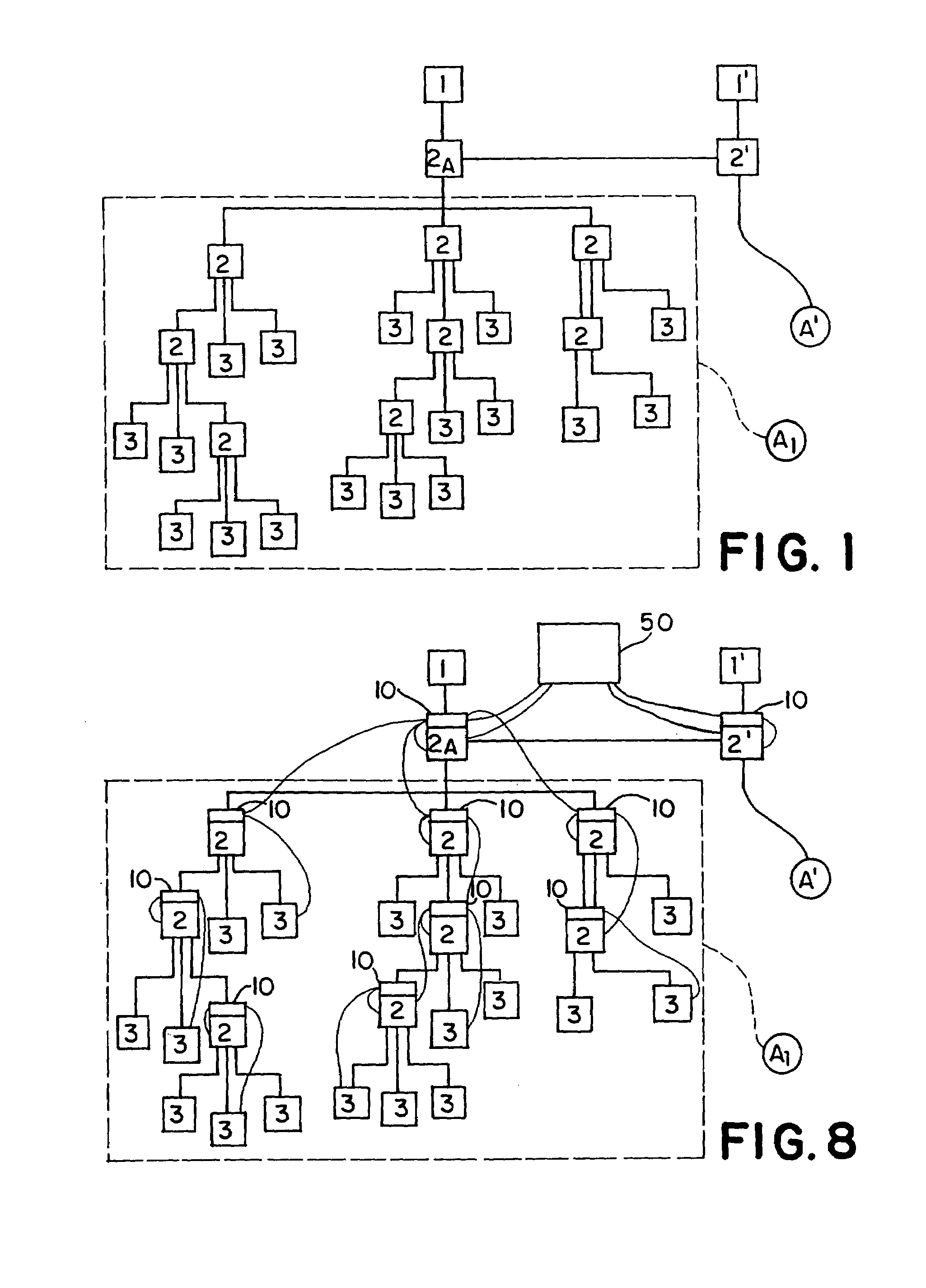
[0043]Referring to the drawings in general, and to FIG. 1 in particular, there is depicted a power distribution system manifesting aspects of the invention. The power distribution system includes at least one power source 1 and a plurality of loads, each of which is designated generally 3. The loads 3 receive power supplied by power sources 1 and perform various functions. Intermediate the power source(s) and the loads are a plurality of power nodes, each of which has been designated generally 2. Conductive branches carry electrical power supplied by sources 1 to selected nodes 2 for distribution by other branches to selected loads 3 or to further nodes 2, which in turn may feed selected loads 3 or even further nodes 2 associated with additional loads 3, etc.

[0044]Rectangular dashed line A1 in FIG. 1 surrounds a plurality of nodes 2 and loads 3 fed primarily from one power source through a power node control center designated generally 2a and depicted schematically. The grouping of ...


PUM


Abstract

An electrical modular power node comprising a power bus backplane containing a plurality of bus bars, at least some of which are connectable to at least one power source, each bus bar having a plurality of terminals at regular intervals along the bus bar, each terminal being in a standard position in a pattern with terminals from the other bus bars and all terminal patterns being in a standard orientation on the backplane, and a plurality of functional modules, each housing circuitry having at least one connector for a connection to at least one terminal on one of the bus bars.

Description

FIELD OF THE INVENTION[0001]This invention relates to power distribution systems and to methods and apparatus for controlling and protecting such power distribution systems, with emphasis on power distribution systems used in both military and commercial nautical applications and large land transportation vehicles.DESCRIPTION OF PRIOR ART[0002]Electrical power distribution systems normally include power sources and many loads, with loads connected to the sources by branches. Power from a source is frequently processed in some way, and possibly various ways, before it is provided to each of the various loads. The locations of circuit elements for processing power may be called “nodes”.[0003]Typically, nodes have been custom-tailored to fit a particular need of the electrical power distribution system at a particular location. One type of node is a power panel.[0004]Power systems may generally be characterized as low voltage or high voltage power systems. For purposes herein low volta...

Claims


Application Information

Patent Timeline
IPC IPC(8): G06F13/14G05D3/12
CPCH05K7/1457H02B1/21H02B1/056
Inventor YKEMA, JOHN I.
Owner L 3 COMM SPD TECH
Why Eureka
Try Eureka