Super-critical refrigerant cycle system and water heater using the same

a cycle system and super-critical technology, applied in the direction of machine operation, lighting and heating apparatus, heat pump, etc., can solve the problems of reducing the life of components increasing the production cost of the heat pump cycle, and abnormally increasing the temperature of the refrigerant discharged from the refrigerant compressor, etc., to achieve the effect of increasing the heat-exchange amount of the internal heat exchanger, restricting the heat-exchange amount of the internal heat exchang

Inactive Publication Date: 2006-07-18
DENSO CORP
View PDF9 Cites 22 Cited by
  • Summary
  • Abstract
  • Description
  • Claims
  • Application Information

AI Technical Summary

Benefits of technology

[0007]The present invention has been made in view of the above problem, and its object is to provide a super-critical refrigerant cycle system capable of preventing a temperature of refrigerant discharged from a refrigerant compressor from being abnormally increased without adding a dedicated component for controlling a heat-exchange amount of an internal heat exchanger.
[0008]According to the present invention, in a super-critical refrigerant cycle system, a refrigerant compressor compresses gas refrigerant to a pressure equal to or higher than the critical pressure of the refrigerant, a heating heat exchanger is disposed for heating a fluid by performing heat-exchange between the fluid and the refrigerant discharged from the refrigerant compressor, an internal heat exchanger is disposed for performing heat-exchange between refrigerant flowing out from the heating heat exchanger and refrigerant flowing toward the refrigerant compressor from a refrigerant evaporator, and a decompression valve is disposed for decompressing refrigerant from the internal heat exchanger and for supplying the decompressed refrigerant to the refrigerant evaporator. In the super-critical refrigerant cycle system, a controller controls a valve open degree of the decompression valve to control a pressure of high-pressure side refrigerant before being decompressed, such that a difference between a refrigerant outlet temperature and a fluid inlet temperature in the heating heat exchanger is set in a predetermined temperature range. Thus, the pressure of high-pressure side refrigerant discharged from the refrigerant compressor is adjusted by the valve open degree of the decompression valve. When low-temperature fluid flows into the heating heat exchanger, that is, when heat-exchange capacity of the internal heat exchanger is not required so much, the heat-exchange amount of the internal heat exchanger can be restricted. At this time, since the difference between the inlet fluid temperature and the outlet refrigerant temperature in the heating heat exchanger is set in the predetermined range, the outlet temperature of refrigerant becomes lower in the heating heat exchanger. Thus, a difference between the outlet refrigerant temperature in the heating heat exchanger and the temperature of refrigerant flowing out from the refrigerant evaporator becomes smaller, thereby restricting the heat-exchange amount of the internal heat exchanger.
[0009]On the other hand, when high-temperature fluid flows into the heating heat exchanger, that is, when large heat-exchanging capacity is required in the internal heat exchanger, the heat-exchanging amount of the internal heat exchanger is increased. That is, at this time, the outlet refrigerant temperature in the heating heat exchanger becomes higher, and the difference between the outlet refrigerant temperature in the heating heat exchanger and the temperature of refrigerant flowing out from the refrigerant evaporator becomes larger, thereby increasing the heat-exchanging amount of the internal heat exchanger. Thus, the internal heat exchanger is controlled so that the heat-exchanging amount of the internal heat exchanger is increased only when the effect of the internal heat exchanger can be performed. Therefore, the temperature of refrigerant discharged from the refrigerant compressor can be restricted from being uselessly increased, thereby increasing lives of components of the refrigerant cycle system while restricting production cost thereof.
[0010]The internal heat exchanger includes a first refrigerant heat-exchanging part disposed between the outlet of the heating heat exchanger and the decompression valve, and a second refrigerant heat-exchanging part disposed between an outlet of the refrigerant evaporator and a suction port of the refrigerant compressor. Preferably, the controller controls the valve open degree of the decompression valve such that a deference between an outlet temperature of refrigerant in the second refrigerant heat-exchanging part of the internal heat exchanger and an inlet temperature of refrigerant in the second refrigerant heat-exchanging part is set smaller than a predetermined temperature. Accordingly, it can prevent the refrigerant temperature discharged from the refrigerant compressor from being excessively increased.
[0011]Preferably, an accumulator disposed between the refrigerant evaporator and the second refrigerant heat-exchanging part of the interior heat exchanger has a storage chamber for temporarily storing refrigerant flowing from the refrigerant evaporator, and an outlet pipe inserted into the accumulator for mainly supplying gas refrigerant from the storage chamber to the refrigerant compressor through the second refrigerant heat-exchanging part of the internal heat exchanger. Further, the outlet pipe has an opening at its top end in the storage chamber, from which gas refrigerant is introduced from the storage chamber into the outlet pipe, an oil return hole at its lower portion in the storage chamber for introducing an oil in the refrigerant from the storage chamber into the outlet pipe, and a liquid-refrigerant return hole at its upper portion upper than the oil return hole in the storage chamber for introducing liquid refrigerant from the storage chamber into the outlet pipe. Here, the liquid-refrigerant return hole can be constructed by at least a single hole. Further, the liquid-refrigerant return hole is provided at a position which becomes equal to or lower than a liquid refrigerant surface in the storage chamber when the temperature of the fluid flowing into the heating heat exchanger is low, and which becomes higher than the liquid-refrigerant surface in the storage chamber when the temperature of the fluid flowing into the heating heat exchanger is high. Accordingly, the liquid refrigerant returning amount can be suitably adjusted, and the refrigerant temperature discharged from the refrigerant compressor can be readily adjusted.

Problems solved by technology

However, when the internal heat exchanger is added, the temperature of refrigerant discharged from the refrigerant compressor is abnormally increased, thereby extremely reducing lives of components of the heat pump cycle.
Therefore, a heat-exchange amount of the internal heat exchanger is required to be controlled, and a dedicated component for controlling the heat-exchange amount of the internal heat exchanger is required to be added, thereby increasing production cost of the heat pump cycle.

Method used


Image

  • Super-critical refrigerant cycle system and water heater using the same
  • Super-critical refrigerant cycle system and water heater using the same
  • Super-critical refrigerant cycle system and water heater using the same

Examples


first embodiment

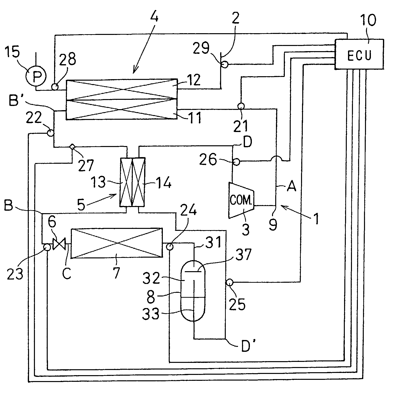
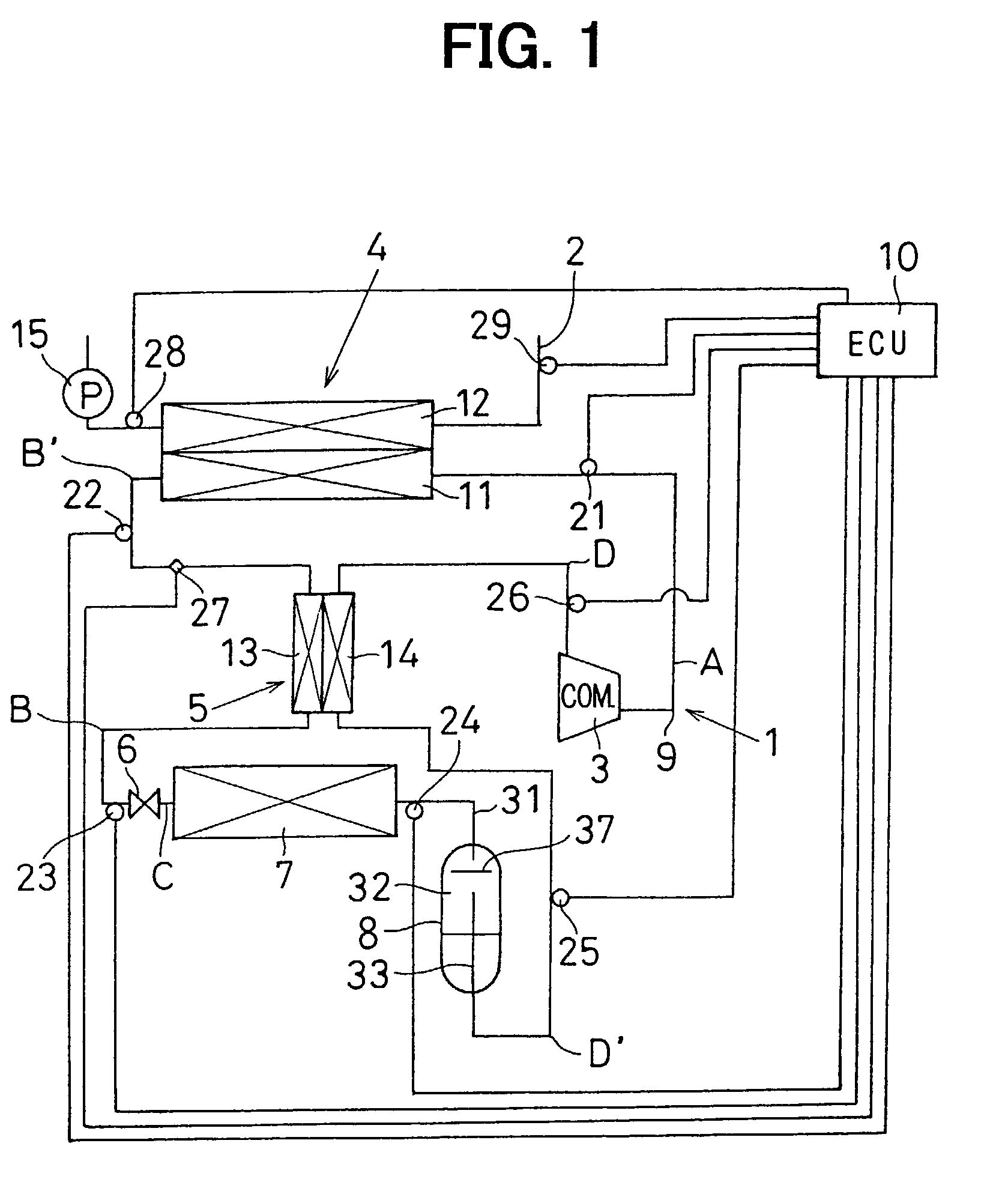
[0022]A heat-pump water heater according to the first embodiment is an electric water heater mainly operated at night using midnight power that is cheaper in running cost, for example. As shown in FIG. 1, the heat-pump water heater includes a heat pump unit 1 used as a heat source for heating water, a hot water pipe 2, and an electronic control unit (ECU) 10 for electronically controlling actuators of the heat pump unit 1 and the hot water pipe 2. The hot water pipe 2 is for supplying water (fluid) heated by the heat pump unit 1, to a hot water tank (not shown), or to a bathroom and a washroom. In the first embodiment, the heat-pump water heater is constructed by a super-critical vapor-compression refrigerant cycle system.

[0023]The heat pump unit 1 includes a refrigerant compressor 3, a water-refrigerant heat exchanger (radiator) 4, an internal heat exchanger 5, a decompression valve 6, a refrigerant evaporator 7, an accumulator 8 and refrigerant pipe 9 connecting these components i...

second embodiment

[0044]In the second embodiment, the structure of the accumulator 8 shown in FIG. 1 is described in detail. As shown in FIG. 8A, the accumulator 8 includes a container body 30 having an elliptical cross-section, an inlet pipe 31 for introducing refrigerant into the container body 30 from the refrigerant evaporator 7, a storage chamber 32 for temporarily storing refrigerant flowing into the container body 30, an outlet pipe 33 for supplying the refrigerant stored in the storage chamber 32 to the suction side of the refrigerant compressor 3, and the like. The outlet pipe 33 is connected to the suction side of the refrigerant compressor 3 outside the storage chamber 32 of the accumulator 8.

[0045]An opening (gas-refrigerant return opening) 34 is provided on the outlet pipe 33 at its top end inside the storage chamber of the accumulator 8. An oil return hole 35 for introducing lubricating oil (e.g., refrigerator oil such as PAG) into the outlet pipe 33 from the storage chamber 32 is provi...


PUM


Abstract

In a heat-pump water heater with a super-critical refrigerant cycle, a valve open degree of a decompression valve is controlled to control a pressure of high-pressure side refrigerant so that a temperature difference between refrigerant flowing out from the water-refrigerant heat exchanger and water flowing into a water-refrigerant heat exchanger is set in a predetermined temperature range. Thus, the pressure of high-pressure side refrigerant in the super-critical refrigerant cycle can be controlled, thereby suitably adjusting heat-exchange performance of an internal heat exchanger, and restricting the temperature of refrigerant discharged from the refrigerant compressor from being uselessly increased.

Description

CROSS-REFERENCE TO RELATED APPLICATION[0001]This application is related to and claims priority from Japanese Patent Application No. 2001-307534 filed on Oct. 3, 2001, the content of which is hereby incorporated by reference.BACKGROUND OF THE INVENTION[0002]1. Field of the Invention[0003]The present invention relates to a super-critical refrigerant cycle system in which pressure of refrigerant discharged from a refrigerant compressor is higher than the critical pressure of refrigerant. More particularly, the present invention relates to improvement of heat-exchange performance in a heat-pump water heater including a water-refrigerant heat exchanger where water to be used is heated by performing heat-exchange with high-pressure side refrigerant discharged from the refrigerant compressor.[0004]2. Description of Related Art[0005]As disclosed in JP-A-2001-82803, a conventional heat-pump water heater includes a water-refrigerant heat exchanger for heating water to be used by performing he...

Claims


Application Information

Patent Timeline
Patent Type & Authority Patents(United States)
IPC IPC(8): F25B27/00F25B9/00F25B30/02F25B31/00F25B40/00F25B43/00
CPCF25B9/008F25B43/006F25B30/02F25B2700/21175F25B31/004F25B40/00F25B2309/061F25B2339/047F25B2600/02F25B2600/17F25B2600/2513F25B2700/195F25B2700/2103F25B2700/21152F25B2700/21161F25B2700/21163
Inventor SAKAKIBARA, HISAYOSHI
Owner DENSO CORP
Why Eureka
Try Eureka