Multi-layer gate stack structure comprising a metal layer for a FET device, and method for fabricating the same

a technology of fieldeffect transistor and gate stack structure, which is applied in the direction of electrical apparatus, semiconductor devices, radio frequency controlled devices, etc., can solve the problems of unsuitable gate dielectric to resist a longer overetching, unfavorable increase in wordline resistance, and high gate stack structure, etc., to achieve the effect of reducing the final gate stack structure heigh

Inactive Publication Date: 2006-07-18
NAN YA TECH +1
View PDF0 Cites 9 Cited by
  • Summary
  • Abstract
  • Description
  • Claims
  • Application Information

AI Technical Summary

Benefits of technology

[0018]A method is provided for fabricating a multi-layer gate stack structure for a FET device that requires less height of a gate electrode layer stack before patterning and that results in a lower height of the final gate stack structure. A multi-layer gate stack structure for a FET device also is provided, wherein the multi-layer gate stack structure results from the inventive method.

Problems solved by technology

Reducing the height of the metal layer would reduce the cross-sectional area thereof, leading to an unfavorable increase in the resistance of the wordline.
Due to its thickness of about 2 nanometers for a typical gate stack structure width of less than 100 nanometers, the gate dielectric is not suitable to resist a longer overetch outside the gate stack structure.
A high gate stack structure is, however, not desirable for process technological reasons, in view of the quality of pattern and fill processes and in view of the range for an implant angle.

Method used


Image

  • Multi-layer gate stack structure comprising a metal layer for a FET device, and method for fabricating the same
  • Multi-layer gate stack structure comprising a metal layer for a FET device, and method for fabricating the same
  • Multi-layer gate stack structure comprising a metal layer for a FET device, and method for fabricating the same

Examples


Embodiment Construction

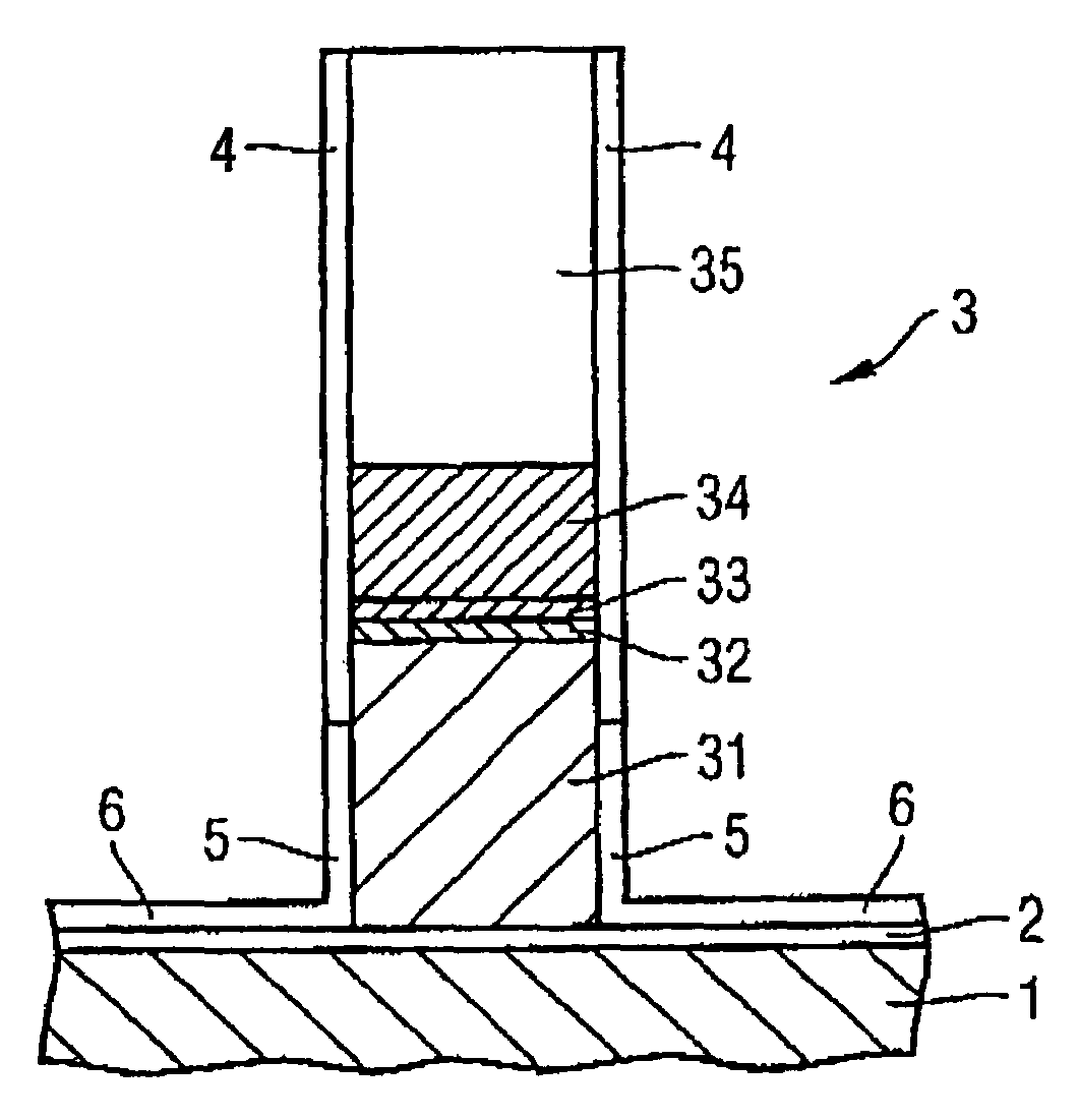
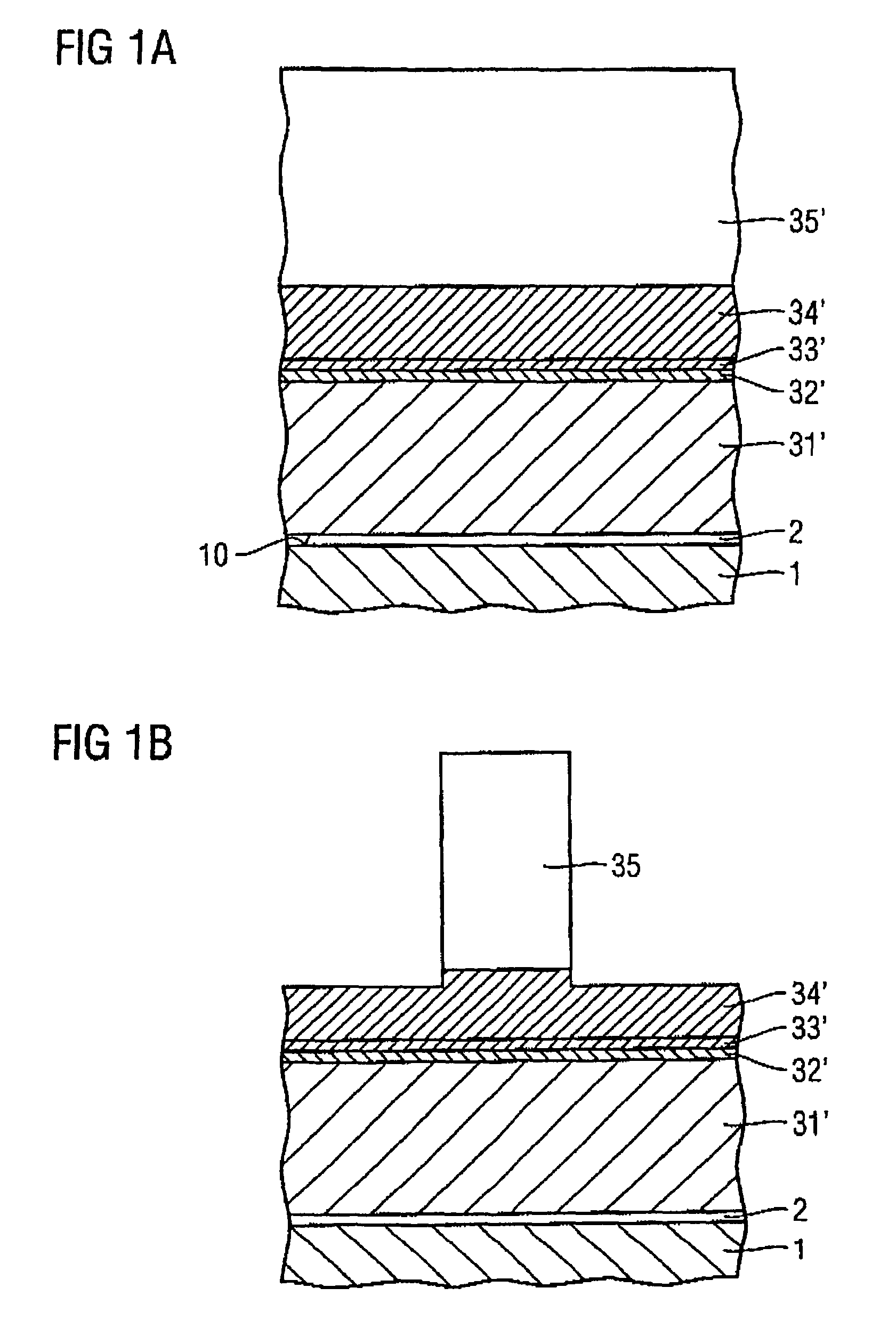
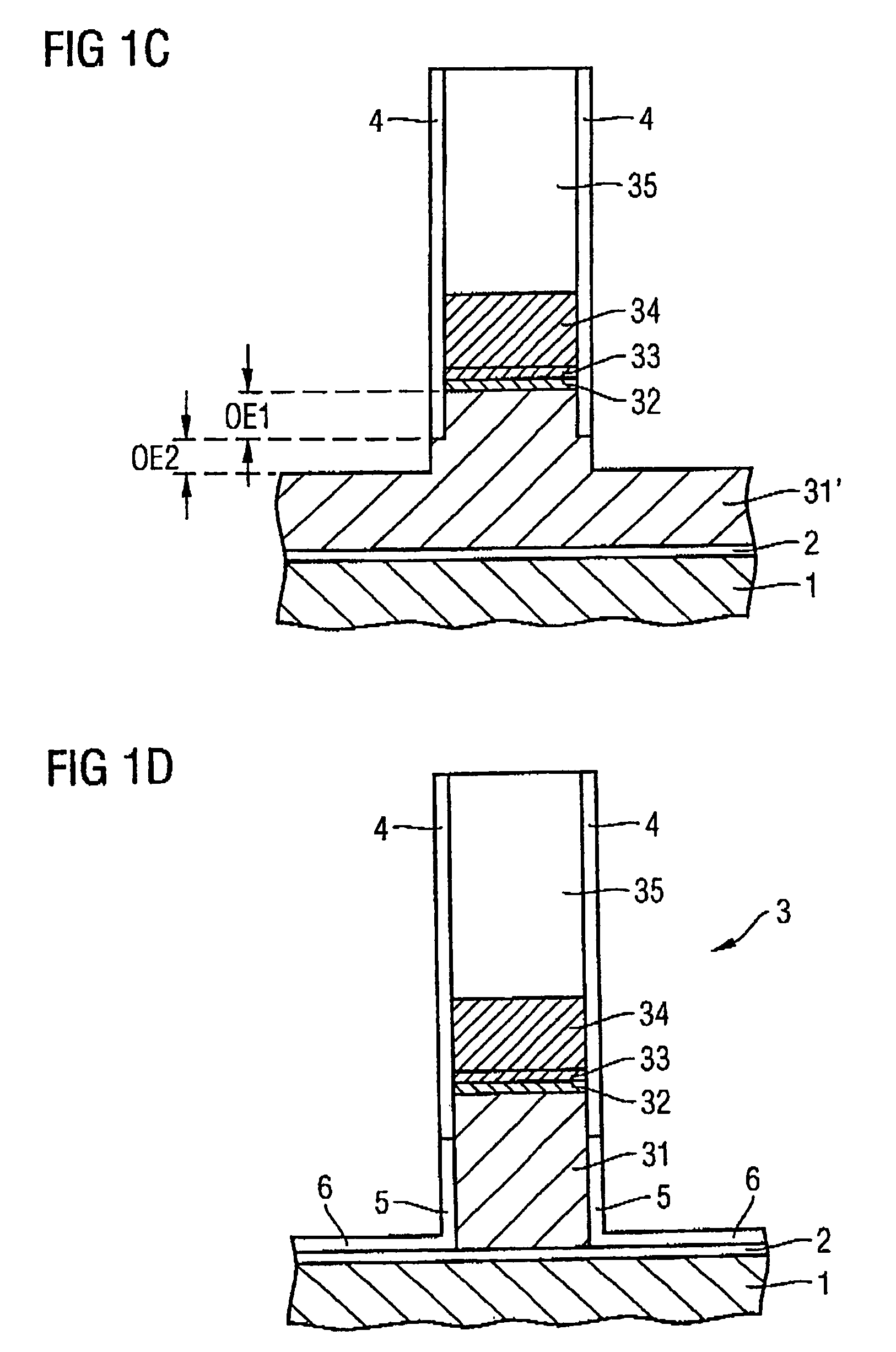
[0026]In the figures, the same reference numbers are used to indicate the same or corresponding elements. Further, each layer is named by its reference number, amended by a prime (′) after deposition. The corresponding patterned layers are marked by the reference numbers without prime. A list of reference symbols utilized consistently in the figures is provided below:

LIST OF REFERENCE SYMBOLS

[0027]1 semiconductor substrate[0028]10 substrate surface[0029]2 gate dielecric[0030]3 gate stack structure[0031]31′ deposited polysilicon layer[0032]31 patterned polysilicon layer[0033]32′ deposited interface layer[0034]32 patterned interface layer[0035]320 interface layer divot[0036]321 pulled back interface layer[0037]33′ deposited barrier layer[0038]33 patterned barrier layer[0039]34′ deposited metal layer[0040]34 patterned metal layer[0041]35′ cap dielectric layer[0042]35 cap dielectric[0043]4 dielectric passivation liner[0044]41 divot fill[0045]5 dielectric sidewall liner[0046]6 sacrificia...


PUM

PropertyMeasurementUnit
widthaaaaaaaaaa
thicknessaaaaaaaaaa
thicknessaaaaaaaaaa

Abstract

A multi-layer gate stack structure of a field-effect transistor device is fabricated by providing a gate electrode layer stack with a polysilicon layer, a transition metal interface layer, a nitride barrier layer and then a metal layer on a gate dielectric, wherein the transition metal is titanium, tantalum or cobalt. Patterning the gate electrode layer stack comprises a step of patterning the metal layer and the barrier layer with an etch stop on the surface of the interface layer. Exposed portions of the interface layer are removed and the remaining portions are pulled back from the sidewalls of the gate stack structure leaving divots extending along the sidewalls of the gate stack structure between the barrier layer and the polysilicon layer. A nitride liner encapsulating the metal layer, the barrier layer and the interface layer fills the divots left by the pulled-back interface layer. The nitride liner is opened before the polysilicon layer is patterned. As the requirement for an overetch into the polysilicon layer during the etch of the metal layer, the barrier layer and the interface layer is omitted, the height of the polysilicon layer can be reduced. The aspect ration of the gate stack structure is improved, the feasibility of pattern and fill processes enhanced and the range of an angle under which implants can be performed is extended.

Description

BACKGROUND[0001]1. Field of the Invention[0002]The present invention relates to a method for fabricating a multi-layer gate stack structure for a field-effect transistor (FET) device and to a multi-layer gate stack structure comprising a metal layer.[0003]2. Background Information[0004]Conventional integrated circuits comprise FET devices with an active area consisting of a source region, a drain region and a channel region between the source region and the drain region formed respectively in a semiconductor substrate beneath a substrate surface of the semiconductor substrate. Gate electrodes of the FET devices are formed above the channel region on a gate dielectric covering the substrate surface.[0005]The gate electrodes of the FET devices are provided by first depositing a sequence of layers for a gate electrode layer stack on the gate dielectric and then patterning the gate electrode layer stack. In memory cell arrays the gate electrodes of a plurality of access transistors of m...

Claims


Application Information

Patent Timeline
Patent Type & Authority Patents(United States)
IPC IPC(8): H01L27/148H01L21/28H01L21/3205H01L31/062
CPCH01L21/28044H01L21/18B82Y40/00
Inventor GOLDBACH, MATTHIASJAKUBOWSKI, FRANKKOEPE, RALFLAY, CHAO-WENSCHUPKE, KRISTINSCHMIDT, MICHAELHUANG, CHENG-CHIH
Owner NAN YA TECH
Why Eureka
Try Eureka