Check patentability & draft patents in minutes with Patsnap Eureka AI!

Modulated reflectance measurement system with fiber laser technology

a reflectance measurement and fiber laser technology, applied in the field of optical methods, can solve the problems of pump laser effectively chasing the probe beam, device sensitive to laser pointing stability, and affecting the accuracy of laser pointing, etc., and achieve the effect of reducing alignment errors

Inactive Publication Date: 2006-07-18
THERMA WAVE INC
View PDF21 Cites 9 Cited by
  • Summary
  • Abstract
  • Description
  • Claims
  • Application Information

AI Technical Summary

Benefits of technology

[0014]The present invention provides a modulated reflectance measurement system that reduces alignment errors between pump and probe beams. The measurement system includes a probe laser and a pump laser, each producing monochromatic light at a different spectrum. A modulator is used to cause the pump laser to have an intensity modulated output, referred to as the pump beam. The probe laser produces an output that is typically non-modulated (i.e., constant intensity). This output is referred to as the probe beam.

Problems solved by technology

Therefore, these devices can be quite sensitive to the laser pointing stability.
This problem is particularly acute when dealing with semiconductor lasers.
A drawback of this methodology is that pump laser effectively chases the probe beam.
Also, any “structure” in the pump or probe beam profile (which is typical of diode lasers), can lead to false maximums in the thermal wave signal, resulting in an error in pump / probe overlap.
Another drawback of the methodology is that the tracker scanning is not performed in a 2-D plane (map) and thus prevents correction of non-symmetrical beams, which is usually the case of diode lasers.
However, in these patents only one laser (probe) is shown to have a fiber connection that only partially improves the overall system performance.
This is particularly important as semiconductor geometries continue to shrink and accurate measurements become increasing difficult to achieve.

Method used


Image

  • Modulated reflectance measurement system with fiber laser technology
  • Modulated reflectance measurement system with fiber laser technology
  • Modulated reflectance measurement system with fiber laser technology

Examples


Embodiment Construction

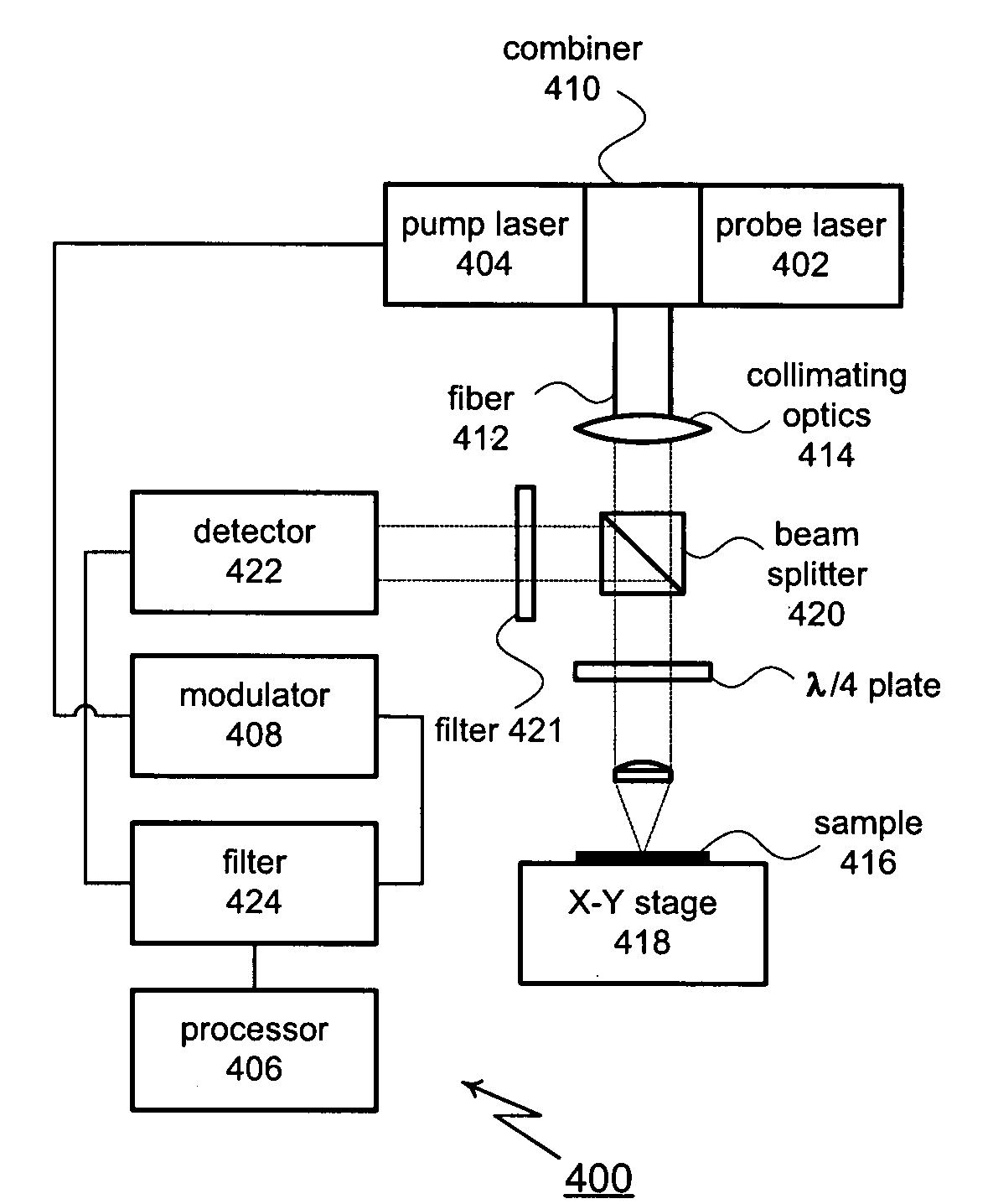
[0029]The present invention provides a modulated reflectance measurement system that reduces alignment errors between pump and probe beams. In FIG. 2, a first possible implementation for the modulated reflectance measurement system is shown and generally designated 200. As shown, modulated reflectance measurement system 200 includes a probe laser 202 and a pump laser 204. Each laser 202, 204 is typically monochromatic and each laser 202, 204 typically operates at a different spectrum. Lasers 202, 204 are generally diode-based or diode-pumped semiconductor lasers. Solid state laser diodes are available that have outputs throughout the entire visible spectrum as well as in the infrared and near UV. Lasers 202, 204 are controlled by a processor 206 and a modulator 208. Modulator 208 causes pump laser 204 to have an intensity modulated output, referred to as the pump beam. Probe laser 202 produces an output that is typically non-modulated (i.e., constant intensity). This output is refer...


PUM


Abstract

A modulated reflectance measurement system includes two diode-based lasers for generating a probe beam and an intensity modulated pump beam. The pump and probe beams are joined into a collinear beam using a laser diode power combiner. One or more optical fibers are used to transport the beams either before and / or after they are combined. The collinear beam is focused through one or more lenses or other optical components for collimation. The collinear beam is then focused by an objective lens onto a sample. Reflected energy returns through an objective and is redirected by a beam splitter to a detector. A lock-in amplifier converts the output of the detector to produce quadrature (Q) and in-phase (I) signals for analysis. A processor uses the Q and / or I signals to analyze the sample.

Description

PRIORITY CLAIM[0001]The present application claims priority to U.S. Provisional Patent Application Ser. No. 60 / 390,752, filed Jun. 21, 2002, the disclosure of which is incorporated herein by reference.TECHNICAL FIELD[0002]The subject invention relates generally to optical methods for inspecting and analyzing semiconductor wafers and other samples. In particular, the subject invention relates to methods for increasing the accuracy and flexibility of systems that use modulated optical reflectivity to analyze semiconductor wafers.BACKGROUND OF THE INVENTION[0003]There is a great need in the semiconductor industry for metrology equipment that can provide high resolution, nondestructive evaluation of product wafers as they pass through various fabrication stages. In recent years, a number of products have been developed for the nondestructive evaluation of semiconductor samples. One such product has been successfully marketed by the assignee herein under the trademark Therma-Probe. This ...

Claims


Application Information

Patent Timeline
IPC IPC(8): G01N21/00G01N21/55G01N21/63G01N21/95
CPCG01N21/1717G01N21/9501G01N21/636G01N21/55
Inventor NICOLAIDES, LENAFANTON, JEFFREY T.SALNIK, ALEX
Owner THERMA WAVE INC
Features
  • R&D
  • Intellectual Property
  • Life Sciences
  • Materials
  • Tech Scout
  • Unparalleled Data Quality
  • Higher Quality Content
  • 60% Fewer Hallucinations
Learn More