Base-station cell design method and base-station cell design apparatus, and program thereof in mobile communication system

a technology of base station cell and design apparatus, which is applied in the direction of multiplex communication, transmission monitoring, wireless commuication services, etc., can solve the problems of loss estimation, unrealistic processing time to gain a solution, and the size of the area that can be designed within the realistic processing time does not come up to the necessary size of the area by far. , to achieve the effect of fast base station cell design

Inactive Publication Date: 2006-07-18
NEC CORP
View PDF19 Cites 21 Cited by
  • Summary
  • Abstract
  • Description
  • Claims
  • Application Information

AI Technical Summary

Benefits of technology

[0023]Yet another objective of the present invention is to provide the base-station cell design method, and the apparatus and the program thereof that enable a fast base-station cell design by reducing the quantity of the radio-wave analytic processing that accounts for a great majority of the base-station cell design processing.
[0038]Also, a technique of which the throughput is few is employed in the radio-wave propagation characteristic evaluation to be made in adding the base station, and a technique of which the throughput is much, but which is of high-precision, more specifically, a technique such as the ray tracing is applied in the radio-wave propagation characteristic evaluation to be made after addition. The result of the high-precision radio-wave propagation characteristic evaluation, which is made after addition, is put to practical use for estimating the interference quantity in selecting the arrangement location of the base station to be added newly. This allows the quantity of a radio-wave analytic processing that accounts for a great majority of the base-station cell design processing to be reduced, thus enabling a fast base-station cell design.

Problems solved by technology

It has been generalized that the base-station cell design in a cellular system employs a specialized tool; however a covered area of an access point (AP: equivalent to the base station) is extremely narrow, a simple propagation-loss estimation equation employed in a conventional cellular system design is impossible to apply in a wireless LAN system to be installed in the environment where a lot of propagation disturbing objects such as a building exist in a line-of-sight propagation area of a radio wave, and a detailed radio-wave analysis, which took a microscopic structure such as a geographical feature of a target area and the building into consideration, is required.
A ray tracing technique is commonly used as a technique of the high-precision radio-wave analysis; however upon employing the cell design technique of the trial-and-error optimal-arrangement search type as shown in FIG. 17, as the case may be, there is the possibility that it takes an unrealistic processing time to gain a solution because the above technique needs a lot of computations.
Needless to say, by narrowing the service area to be taken as an object of design, the AP number that has to be arranged is reduced, which enables a reduction in the processing time; however the base station number to be arranged per area becomes extremely numerous in a picocell environment like the wireless LAN, as compared with a macrocell / microcell environment in the conventional mobile communication system, whereby the problem occurs that the size of the area that can be designed within the realistic processing time does not come up to the necessary size of the area by far.
However, the result varies anyway, depending upon the AP layout candidate selected firstly, and vague elements such as a perception and an experience of a designer dictate the selection of the AP layout candidate, thus the problem existed that an appropriate cell design was not always possible to guarantee.
The vagueness of the perception / experience of the designer can be excluded in the base-station cell design technique disclosed in the patent document 2; however it was pointed out that the solution did not converge, depending upon pre-setting of parameters such as initial layout, which gave rise to occurrence of an unstable phenomenon such as divergence and oscillation, and the problem existed that if there rose the situation where the convergence of the solution was unpromising, a work had to be done over again from the beginning.

Method used


Image

  • Base-station cell design method and base-station cell design apparatus, and program thereof in mobile communication system
  • Base-station cell design method and base-station cell design apparatus, and program thereof in mobile communication system
  • Base-station cell design method and base-station cell design apparatus, and program thereof in mobile communication system

Examples


Embodiment Construction

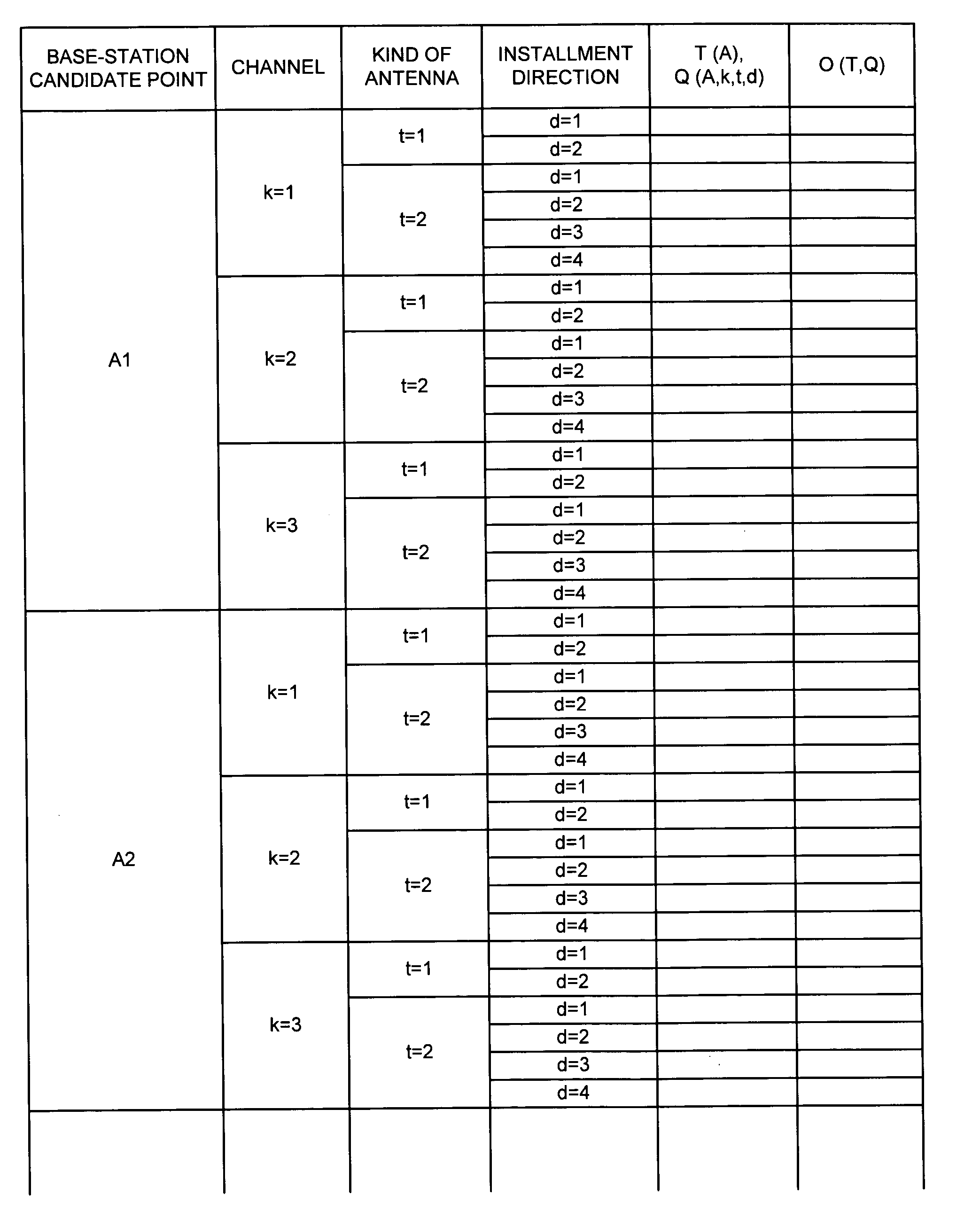
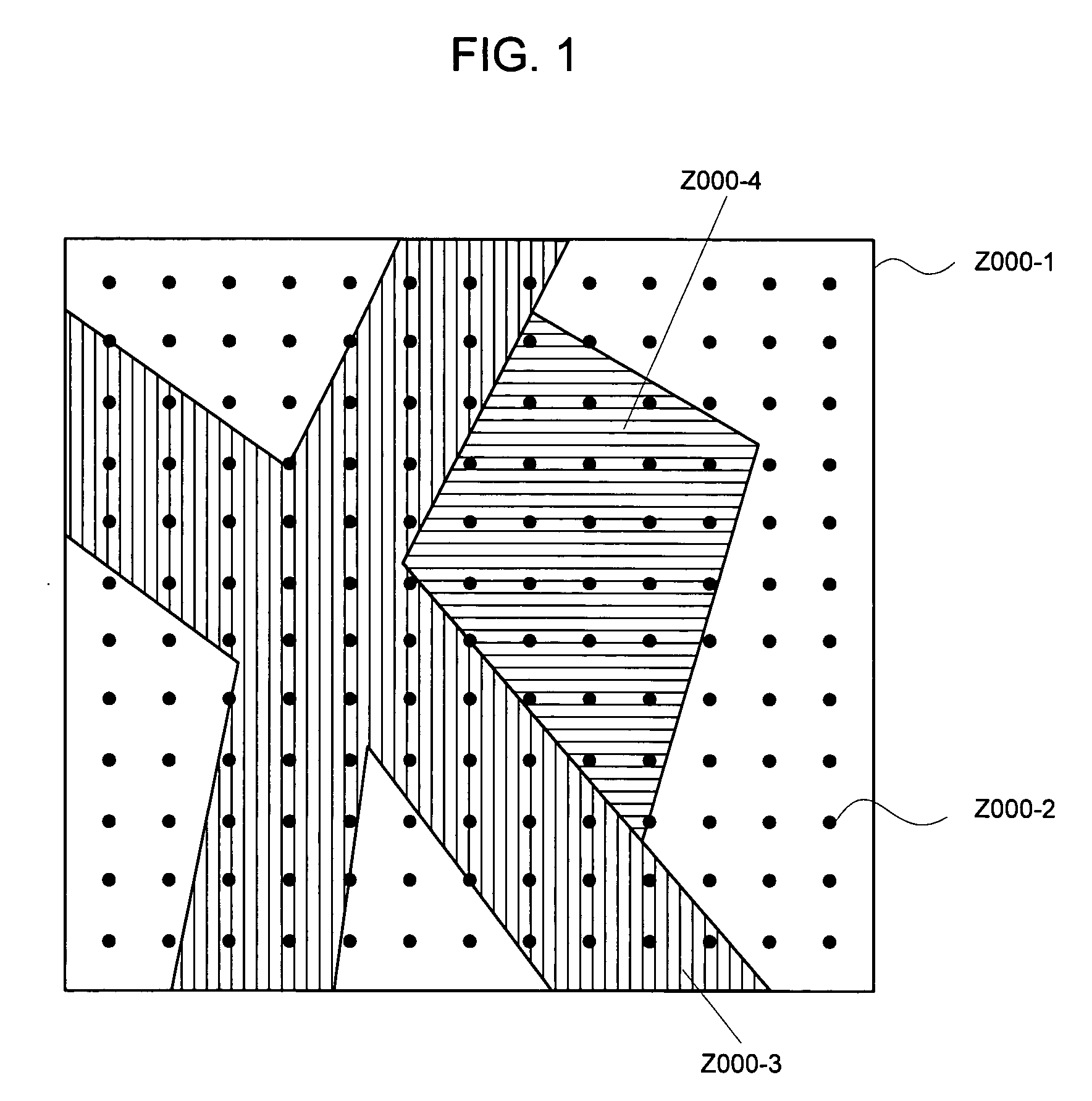
[0060]Embodiments of the present invention will be explained in details below by referring to the accompanied drawings. Firstly, the base-station cell design algorithm of the present invention premises that the service area, the base-station location candidate point, and the traffic distribution are given (for example, the traffic distribution can be estimated from the traffic quantity etc. on a road that exists within a service area Z000-1). FIG. 1 is a view illustrating a setting example of each parameter thereof. Z000-1 represents the service area, and a small black circle Z000-2 indicates one of the base-station location candidate points. Also, there is also a case where the location candidate point is three-dimensionally specified, and there is a case where a plurality of observation points are specified that have an identical XY coordinate, and yet have different Z-axis coordinates respectively. Furthermore, there is a case where the setting is made of the location candidate h...


PUM


Abstract

The above base-station cell design method is for sequentially adding base stations, and a technique of which throughput is few is employed for a radio-wave propagation characteristic evaluation to be made in this addition, and a technique of which the throughput is much, but which is of high-precision, more specifically, a technique such as the ray tracing is applied for the radio-wave propagation characteristic evaluation to be made after addition. The result of the high-precision radio-wave propagation characteristic evaluation to be made after this addition is put to practical use for estimating an interference quantity in selecting the arrangement location of the base station to be added newly. This allows the quantity of the radio wave analytic processing, which accounts for a large majority of the base-station cell design processing, to be reduced, thus enabling a fast base-station cell design.

Description

BACKGROUND OF THE INVENTION[0001]The present invention relates to a base-station cell design method, an apparatus and a program thereof in a radio communication system, and more particular to a base-station cell design technique such as base-station layout and base-station parameter setting in a mobile communication system.[0002]A conventional base-station cell design technique will be explained by use of FIG. 17. Base-station candidates are arranged in locations displayed with black squares A02 to A06 on a service area A11 to evaluate a rate of areas A01, and A07 to A10 to be covered by the above base-station candidate group to a service area A11, i.e. an area coverage ratio. Similarly, the area coverage ratio is evaluated for the other arrangement location as well to repeat its evaluation until a base-station arrangement pattern in which a desired area coverage ratio is reached is obtained. In the event of making base-station installment of a trial-and-error optimal-arrangement se...

Claims


Application Information

Patent Timeline
Patent Type & Authority Patents(United States)
IPC IPC(8): H04Q7/20H04J3/00H04B7/26H04B17/391H04W16/00H04W16/18H04W16/22H04W24/00H04W24/06H04W88/08
CPCH04W16/18H04W16/22
Inventor FURUKAWA, HIROSHIEBATA, KOICHI
Owner NEC CORP
Why Eureka
Try Eureka