Semi-blind transmit antenna array device using feedback information and method thereof in a mobile communication system

a mobile communication system and feedback information technology, applied in the direction of resonant antennas, direction finders using radio waves, instruments, etc., can solve the problems of inability to use raleigh transmission antenna arrays using single paths, inability to use raleigh transmission antenna arrays using a single path for a multi-path system, and inability to transmit unnecessary radiation energy to other mobile stations

Inactive Publication Date: 2006-07-18
SAMSUNG ELECTRONICS CO LTD
View PDF19 Cites 88 Cited by
  • Summary
  • Abstract
  • Description
  • Claims
  • Application Information

AI Technical Summary

Benefits of technology

[0045]It is another object of the present invention to provide a transmit antenna array device and a method thereof suitable for a mobile communication system where a feedback delay time is short and a mobile station roams at a movement speed that is not greatly changed.
[0046]It is a further object of the present invention to provide a transmit antenna array device and a method thereof in which a current forward fading coefficient is estimated from previous forward fading information fed back from a mobile station in a mobile communication system where a feed back delay time is great and the mobile station roams at a movement speed that is not greatly changed.

Problems solved by technology

In this situation, when a transmission is performed toward a desired specific mobile station through a dedicated channel, as opposed to a situation where transmission to all mobile stations is performed using a base station transmission antenna through a common channel, much of the radiation energy except radiation energy for the specified mobile station is useless and the unnecessary radiation energy becomes interference signals to other mobile stations.
The reason for assuming that a single antenna is used in the mobile station is that the mobile station does not typically use an antenna array due to limitations of cost, size, and mobility.
Despite the advantage of simple structure, the Raleigh transmission antenna array using a single path is not feasible for a multi-path system.
The issue is how to determine weights (different from weight vectors).
Thus, it is no use analyzing a received reverse signal to obtain the instant fading coefficient of the forward channel.
However, the blind beam formation has a slightly lower performance than the non-blind beam formation using an optimal weight vector calculated by Eq.
While the Thompson antenna array structure can be used as a transmission antenna array system in a multi-path environment, the use of an average fading power makes it impossible to calculate a precise weight vector.
The limitation of the Thompson antenna array in calculating a precise weight vector decreases the performance of the antenna array system

Method used


Image

  • Semi-blind transmit antenna array device using feedback information and method thereof in a mobile communication system
  • Semi-blind transmit antenna array device using feedback information and method thereof in a mobile communication system
  • Semi-blind transmit antenna array device using feedback information and method thereof in a mobile communication system

Examples


first embodiment (

Basic Type)

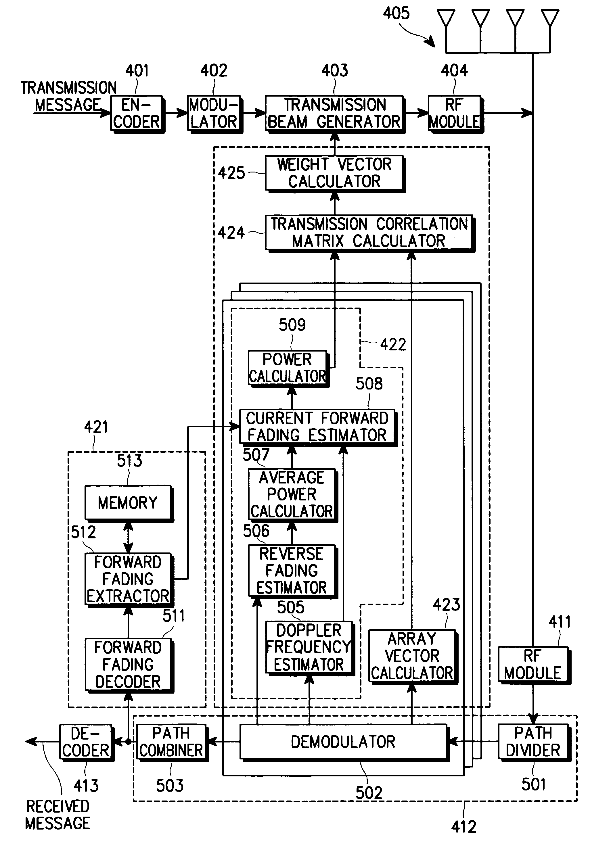
[0134]A transmit antenna array system according to the first embodiment of the present invention is used when the feedback delay time D is 0 or relatively short and the mobile station travels at a low speed. This transmit antenna array system is referred to as a basic type. FIG. 5 is a block diagram of the transmit antenna array system according to the first embodiment and FIG. 10 is a flowchart illustrating a forward fading power calculating operation according to the first embodiment.

[0135]Referring to FIGS. 5 and 10, the path divider 501 of the rake receiver 412 separates a reverse signal for each path, the demodulator 502 in each finger demodulates the reverse signal for each path, and the path combiner 503 combines all finger outputs appropriately in steps 711 and 713. In step 719, the decoder 413 decodes the combined signal, thereby recovering a received message.

[0136]Meanwhile, a forward fading decoder 511 obtains forward fading information that was received from t...

second embodiment (

Prediction Type)

[0138]When the feedback delay time D is rather long, the prediction type can be used which has a means for predicting the current forward fading coefficient from previous feedback forward fading information. A transmit antenna array system according to the second embodiment of the present invention is shown in FIG. 6 and its operation is illustrated in FIG. 11. While any predictor may be used with the same effect for this transmit antenna array system, it is assumed that a linear predictor is provided.

[0139]Referring to FIGS. 6 and 11, the path divider 501 of the rake receiver 412 separates a reverse signal for each path, the demodulator 502 in each finger demodulates a corresponding reverse signal, and the path combiner 503 combines all finger outputs appropriately in steps 811 and 813. In step 821, the decoder 413 decodes the combined signal, thereby recovering a received message.

[0140]Meanwhile, the forward fading decoder 511 obtains forward fading information rec...

third embodiment (

Basic Mixed Type)

[0147]When the feedback delay time D is 0 or relatively short, the first embodiment shows good performance until the movement speed of the mobile station reaches a threshold. However, once the mobile station travels at a speed over the threshold, the performance drastically decreases. To overcome this problem, the blind forward beam formation method can be used when it is determined that the mobile station travels at a speed over the threshold. In the third embodiment, the basic type and the blind forward beam formation method are selectively used according to the movement speed of the mobile station. This scheme is referred to as a basic mixed forward beam formation method.

[0148]FIG. 7 is a block diagram of a transmit antenna array system according to the third embodiment of the present invention and FIG. 12 is a flowchart illustrating the operation of a forward fading power calculator in the transmit antenna array system according to the third embodiment of the pr...


PUM


Abstract

There is provided a transmit antenna array device with at least two antennas and a method thereof in which a transmission beam is appropriately formed based on a weight vector to be transmitted to a specific mobile station in a mobile communication system. For this purpose, a base station device has a reverse processor for processing a reverse signal received through the antenna array, a forward fading information extraction unit for extracting forward fading information from the received reverse signal, a beam formation controller for generating a weight vector for formation of a transmission beam using the forward fading information and the received reverse signal, and a forward processor having a transmission beam generator for generating a transmission beam for a transmission message based on the weight vector. A mobile station device has a forward processor for processing a received forward signal, a forward fading estimator for estimating forward fading information of the forward signal for each path, a forwarding fading encoder for combining the estimated forward fading information and encoding the combined forward fading information, and a reverse processor for multiplexing the encoded forward fading information with a transmission message and feeding back the forward fading information in the multiplexed signal to a base station.

Description

PRIORITY[0001]This application claims priority to an application entitled “Semi-Blind Transmit Antenna Array Device Using Feedback Information and Method Thereof in Mobile Communication System” filed in the Korean Industrial Property Office on Mar. 8, 2000 and assigned Ser. No. 2000-11617, the contents of which are hereby incorporated by reference.BACKGROUND OF THE INVENTION[0002]1. Field of the Invention[0003]The present invention relates generally to an antenna array device and a method thereof in a mobile communication system, and in particular, to a device and method for forming a transmission beam.[0004]2. Description of the Related Art[0005]As the number of mobile subscribers drastically increases, the capacity of the mobile communication systems approaches a saturation point. This means that mobile communication systems are in need of more advanced applications to increase the system capacity, particularly the capacity of a forward link for diverse multimedia services.[0006]T...

Claims


Application Information

Patent Timeline
Patent Type & Authority Patents(United States)
IPC IPC(8): H04B1/38H01Q21/30H04B7/06
CPCH04B7/0617H04B7/0626Y02B60/50H01Q21/30H04W4/12
Inventor CHUN, BYUNG-JINCHOI, JIN-HO
Owner SAMSUNG ELECTRONICS CO LTD
Why Eureka
Try Eureka