Low-power, high-modulation-index amplifier for use in battery-powered device

a high-modulation index, low-power technology, applied in the field of modulation amplifiers, can solve problems such as difficulty in modulating carrier signals, and achieve the effect of reliable and efficient data and power transmission

Inactive Publication Date: 2006-07-18
BOSTON SCI NEUROMODULATION CORP
View PDF19 Cites 76 Cited by
  • Summary
  • Abstract
  • Description
  • Claims
  • Application Information

AI Technical Summary

Benefits of technology

[0010]Yet another embodiment of the invention may be characterized as a method of reliably and efficiently transmitting data and power to an implantable medical device from an external power amplifier. The implantable medical device includes an implanted coil. The external power amplifier includes a primary coil. The method includes the steps of: (1) generating a carrier signal in the power amplifier; (2) inductively coupling the carrier signal from the primary coil to the implanted coil through a high Q (Q≧10) resonant circuit that includes the primary coil and the implanted coil when only power is to be transmitted to the implantable medical device; (3) modulating the carrier signal with data when data is to be transmitted to the implantable medical device; and (4) inductively coupling the modulated carrier signal from the primary coil to the implanted coil through a low Q (Q≦4) resonant circuit that includes the primary coil and the implanted coil. In a preferred implementation, the low Q circuit is obtained by electrically connecting a resistor to the primary coil so as to detune the high Q resonant circuit so that it becomes a low Q circuit.

Problems solved by technology

Disadvantageously, when operating as a tuned resonant circuit, it is difficult to modulate the carrier signal with data having sharp rise and fall times without using a high power modulation amplifier.

Method used


Image

  • Low-power, high-modulation-index amplifier for use in battery-powered device
  • Low-power, high-modulation-index amplifier for use in battery-powered device
  • Low-power, high-modulation-index amplifier for use in battery-powered device

Examples


Embodiment Construction

[0019]The following description is of the best mode presently contemplated for carrying out the invention. This description is not to be taken in a limiting sense, but is made merely for the purpose of describing the general principles of the invention. The scope of the invention should be determined with reference to the claims.

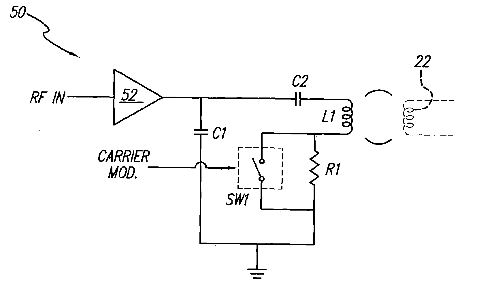
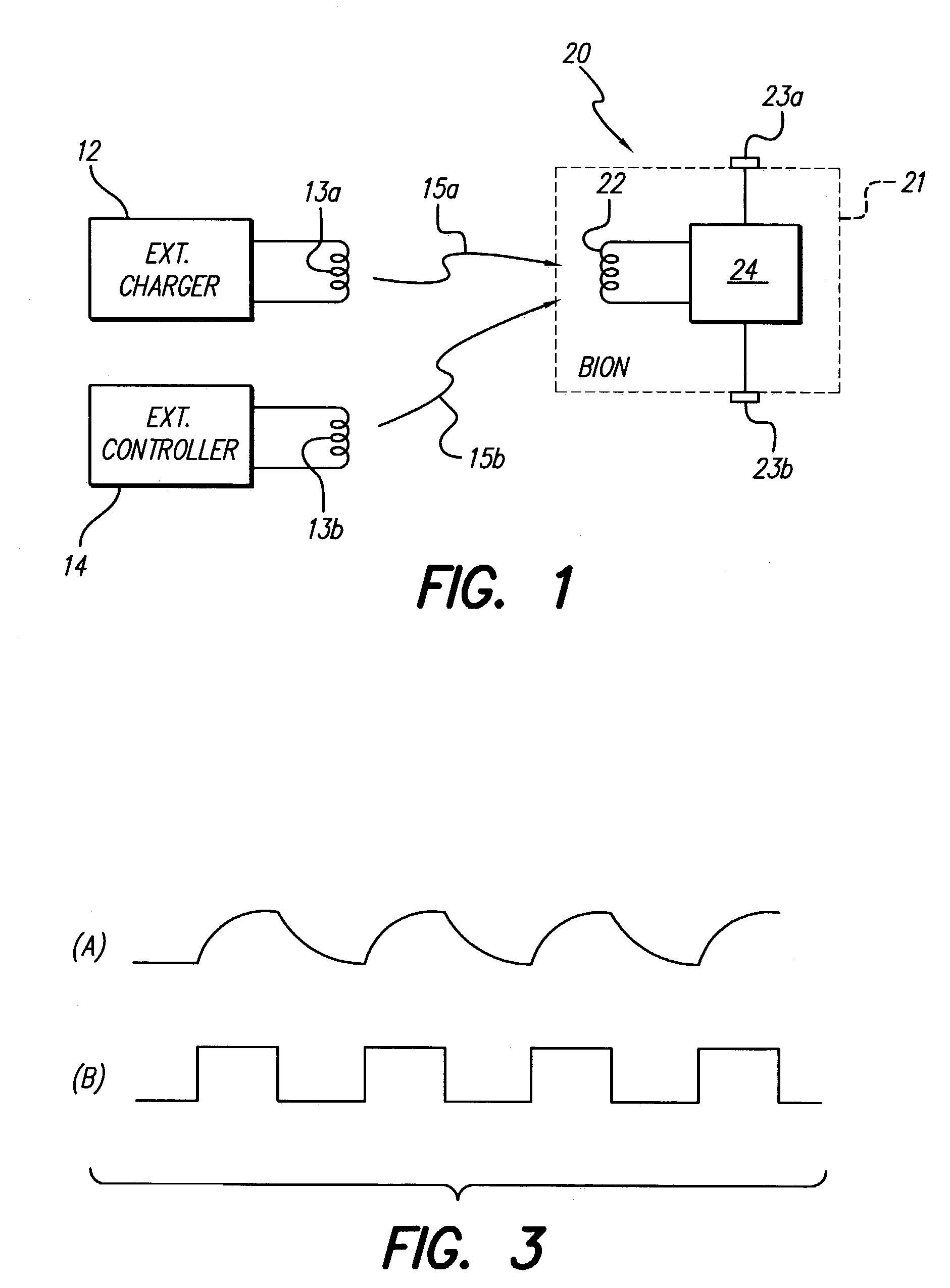
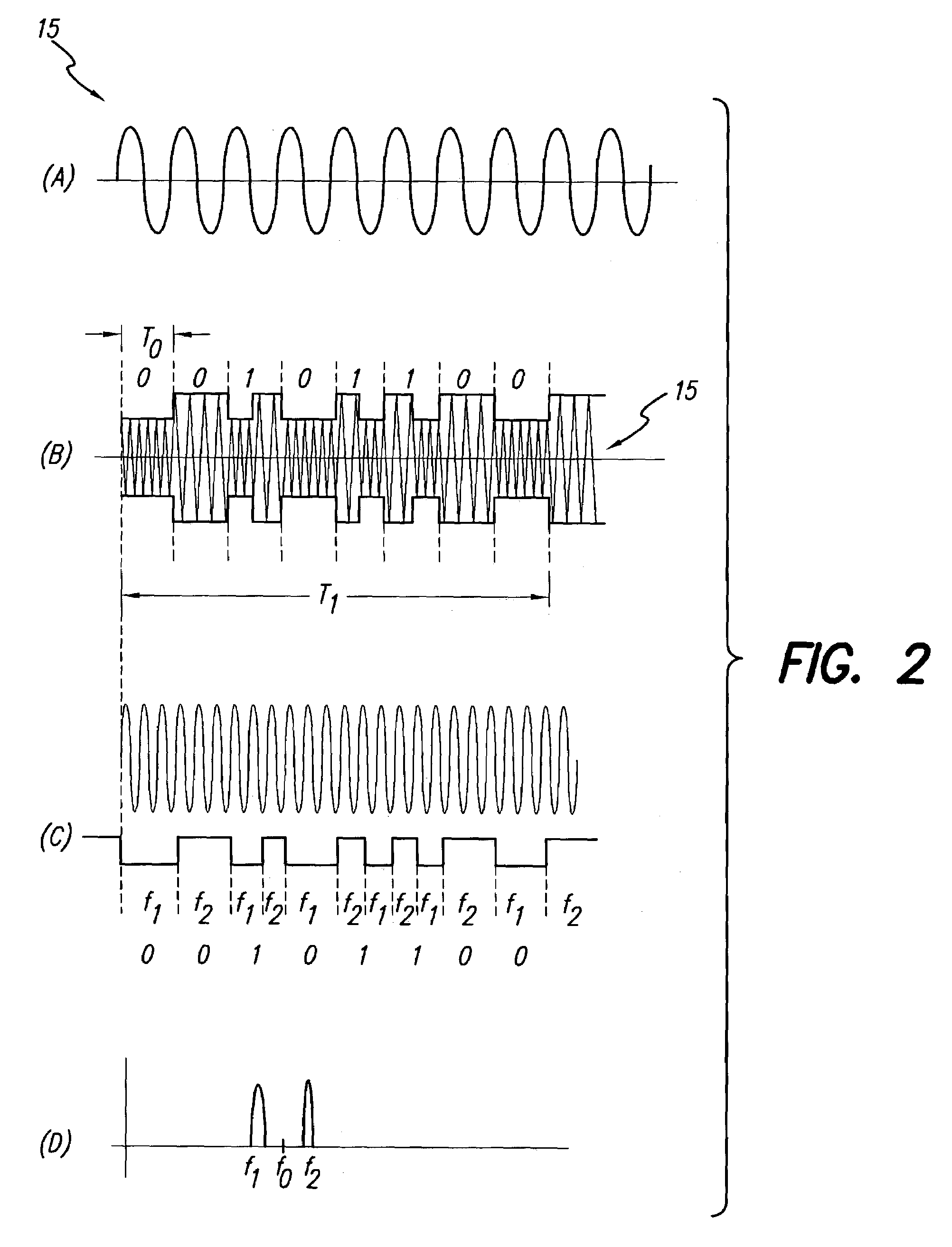
[0020]In order to better understand the present invention, it will first be helpful to provide an overview of an implantable medical device system, e.g., a neural stimulation system, with which the present invention may be used. A functional block diagram that illustrates the main components of such a system is shown in FIG. 1. As seen in FIG. 1, the system includes an implantable BION-type device 20 and one or more external components 12 or 14. The implantable device 20 includes electronic circuitry 24 connected to electrodes 23a and 23b. An implanted coil 22 is also connected to the circuitry 24. All but the electrodes 23a and 23b are housed within an herm...


PUM


Abstract

An external transmitter circuit drives an implantable neural stimulator having an implanted coil from a primary coil driven by a power amplifier. For efficient power consumption, the transmitter output circuit (which includes the primary coil driven by the power amplifier inductively coupled with the implanted coil) operates as a tuned resonant circuit. When operating as a tuned resonant circuit, it is difficult to modulate the carrier signal with data having sharp rise and fall times without using a high power modulation amplifier. Sharp rise and fall times are needed in order to ensure reliable data transmission. To overcome this difficulty, the present invention includes an output switch that selectively inserts a resistor in the transmitter output coil circuit in order to de-tune the resonant circuit only during those times when data modulation is needed. Such de-tuning allows sharp rise and fall times in the data modulation without the need for using a high power modulation amplifier. Because data modulation is typically needed for only a small percent of the time that a carrier signal is present, it is thus possible using the present invention to achieve reliable data modulation, transmission and reception without having to use a high power modulation amplifier in the transmitter.

Description

[0001]The present application is a Divisional of U.S. application Ser. No. 09 / 945,303, filed Aug. 31, 2001 now U.S. Pat. No. 6,591,139; which claims the benefit of U.S. Provisional Application Ser. No. 60 / 230,399, filed Sep. 6, 2000, which applications are incorporated herein by reference.BACKGROUND OF THE INVENTION[0002]The present invention relates to modulation amplifiers, and more particularly to a low-power, high-modulation-index amplifier suitable for use in battery-powered devices, e.g., an implantable battery-powered medical device.[0003]Modulation is the process of varying some characteristic of one wave in accordance with another wave. In radio broadcasting, for example, some stations use amplitude modulation (AM), while other stations use frequency modulation (FM). In television, the video portion of the program is amplitude modulated and the audio portion is frequency modulation. In other types of transmissions, such as are used with satellite transmissions or transmissi...

Claims


Application Information

Patent Timeline
Patent Type & Authority Patents(United States)
IPC IPC(8): A61N1/02H04B5/00A61N1/372A61N1/378
CPCA61N1/37211A61N1/37276A61N1/3787Y10S128/902Y10S128/903
Inventor LOFTIN, SCOTT MMCCLURE, KELLY H
Owner BOSTON SCI NEUROMODULATION CORP
Why Eureka
Try Eureka