
Heat regenerative engine

a heat regenerative engine and engine technology, applied in the field of steam engines, can solve the problems of complex engine design proposals, high cost, and large engine expense, and achieve the effects of high efficiency, high efficiency, high efficiency and compactness

Inactive Publication Date: 2006-07-25
CYCLONE POWER TECH
View PDF6 Cites 26 Cited by
  • Summary
  • Abstract
  • Description
  • Claims
  • Application Information

AI Technical Summary

Benefits of technology

"The present invention is a highly efficient engine that uses water as the working fluid and lubricant. It consists of a condenser, steam generator, and main engine section with valves, cylinders, pistons, pushrods, and a main bearing. The engine is controlled by a rocker and cam design that opens and closes a needle type valve in the engine head. The speed and torque of the engine are controlled by the rocker and cam design. The engine is designed to be compact and efficient, with a high-speed and high-torque output."

Problems solved by technology

Environmental concerns have prompted costly, complex technological proposals in engine design.
However, the expense and size of fuel cell engines, as well as the cost of creating, storing, and delivering fuel grade hydrogen disproportionately offsets the environmental benefits.
As a further example, clean running electric vehicles are limited to very short ranges, and must be regularly recharged by electricity generated from coal, diesel or nuclear fueled power plants.
In small sizes, gas turbines are costly to build, run and overhaul.
Diesel and gas internal combustion engines are efficient, lightweight and relatively inexpensive to manufacture, but they produce a significant level of pollutants that are hazardous to the environment and the health of the general population and are fuel specific.
The single tubes used to pipe super heated steam to the engine have a significant exposed surface area, which limits pressure and temperature levels.
The less desirable lower pressures and temperatures, at which water can easily change state between liquid and gas, requires a complicated control system.
While Steam Engines are generally bulky and inefficient, they tend to be environmentally clean.

Method used


Image

  • Heat regenerative engine
  • Heat regenerative engine
  • Heat regenerative engine

Examples


Embodiment Construction

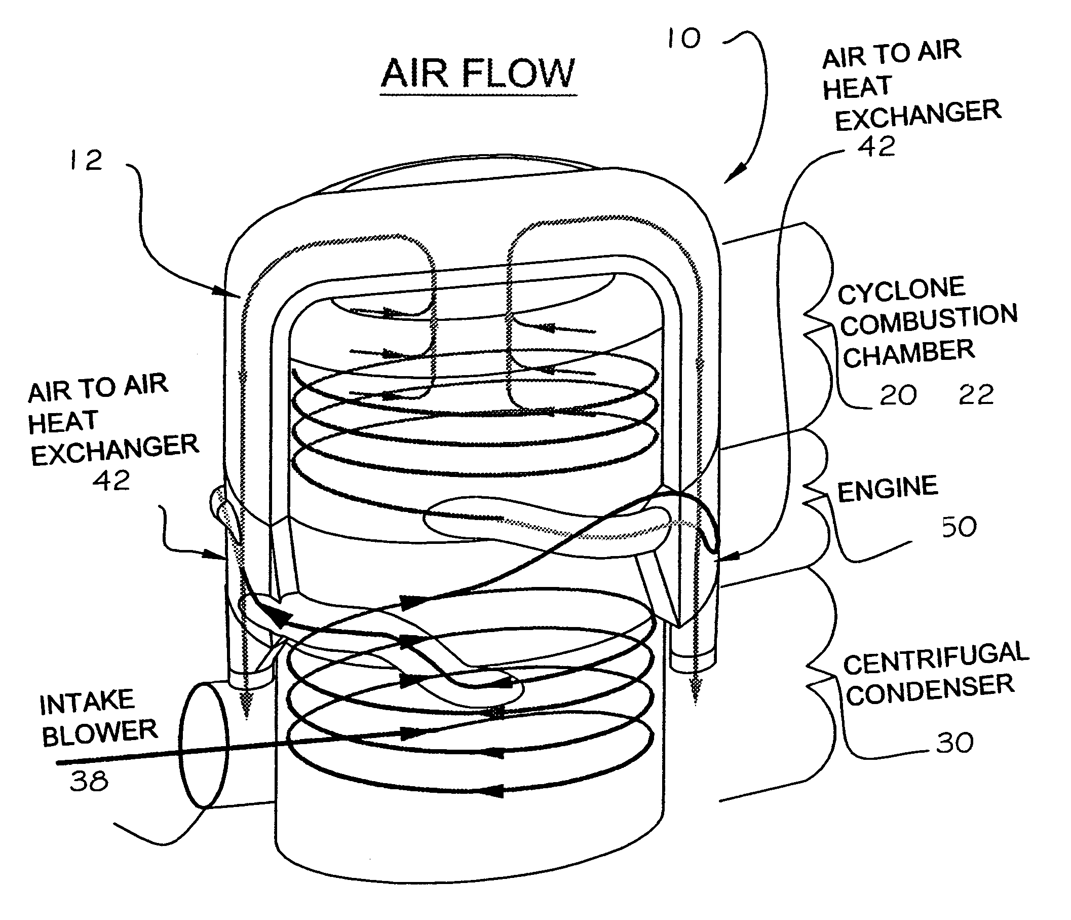
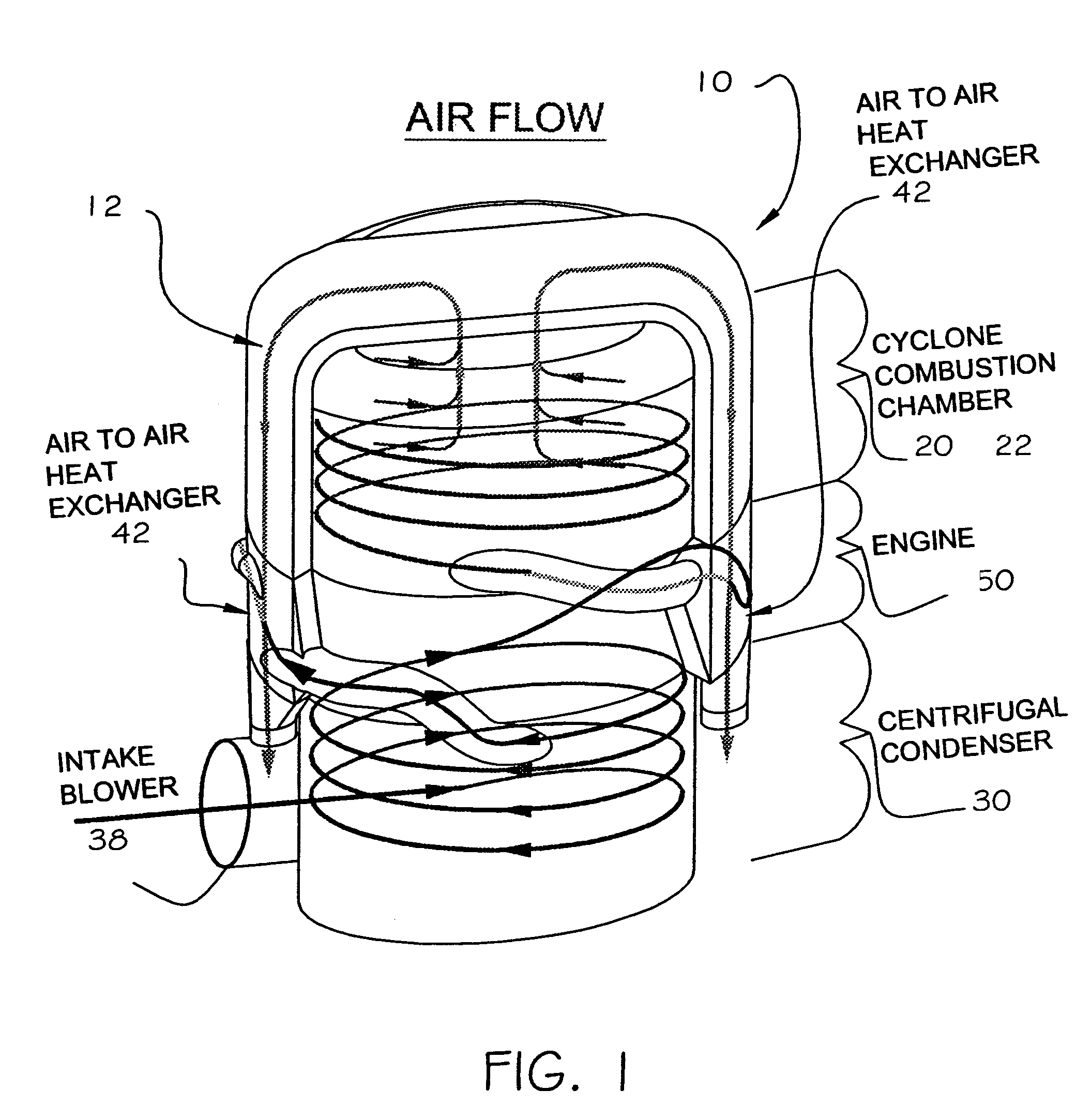
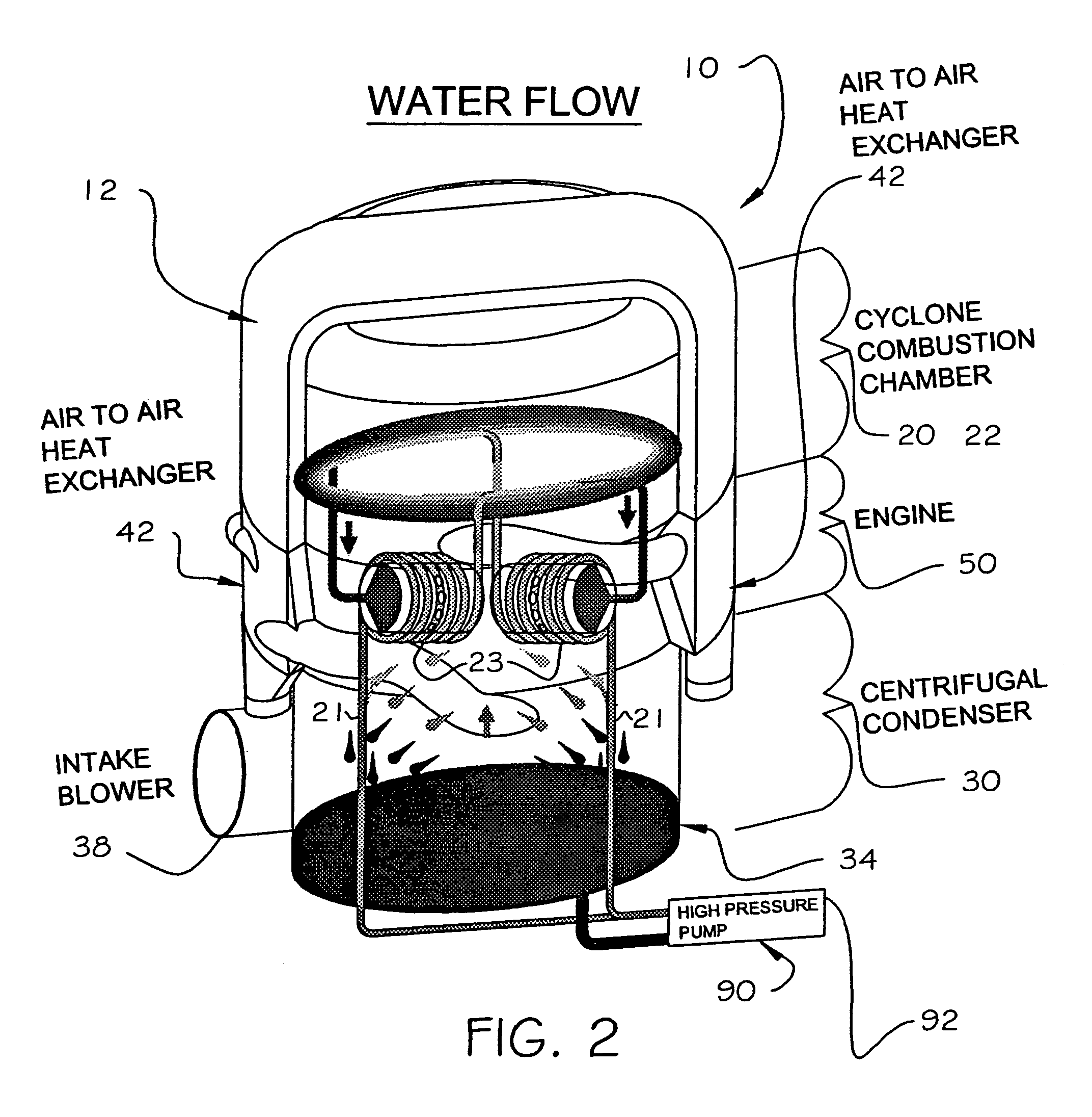
[0032]The present invention is directed to a radial steam engine and is generally indicated as 10 throughout the drawings. Referring initially to FIGS. 1 and 2, the engine 10 includes a steam generator 20, a condenser 30 and a main engine section 50 comprising cylinders 52, valves 53, pistons 54, push-rods 74, crank cam 61 and a crankshaft 60 extending axially through a center of the engine section.

[0033]In operation, ambient air is introduced into the condenser 30 by intake blowers 38. The air temperature is increased in two phases before entering a cyclone furnace 22 (referred to hereafter as “combustion chamber”). The condenser 30 is a flat plate dynamic condenser with a stacked arrangement of flat plates 31 surrounding an inner core. This structural design of the dynamic condenser 30 allows for multiple passes of steam to enhance the condensing function. In a first phase, air enters the condenser 30 from the blowers 38 and is circulated over the condenser plates 31 to cool the o...


PUM


Abstract

A heat regenerative engine uses water as both the working fluid and the lubricant. In operation, water is pumped from a collection pan and through a coil around a cylinder exhaust port, causing the water to be preheated by steam exhausted from the cylinder. The preheated water then enters a steam generator and is heated by a combustion chamber to produce high pressure super heated steam. Air is preheated in a heat exchanger and is then mixed with fuel from a fuel atomizer. An igniter burns the atomized fuel as the flames and heat are directed in a centrifuge within the combustion chamber. The speed and torque of the engine are controlled by a rocker and cam arrangement which opens a needle-type valve to inject high pressure super heated steam into a cylinder having a reciprocating piston therein. The injected steam expands in an explosive action on the top of the piston at high pressure forcing the piston down and drivingly rotating a linked crank cam and crankshaft. Exhaust steam is directed through a centrifugal condenser having an arrangement of flat plates. Cooling air from blowers circulates through the flat plates to condense the steam to a liquid state. The water condensation is returned to the collection pan for subsequent use in steam generation.

Description

BACKGROUND OF THE INVENTION[0001]1. Field of the Invention[0002]The present invention is directed to a steam engine and, more particularly, to a heat regenerative engine which uses water as the working fluid, as well as the lubricant, and wherein the engine is highly efficient, environmentally friendly and adapted for multi-fuel use.[0003]2. Discussion of the Related Art[0004]Environmental concerns have prompted costly, complex technological proposals in engine design. For instance, fuel cell technology provides the benefit of running on clean burning hydrogen. However, the expense and size of fuel cell engines, as well as the cost of creating, storing, and delivering fuel grade hydrogen disproportionately offsets the environmental benefits. As a further example, clean running electric vehicles are limited to very short ranges, and must be regularly recharged by electricity generated from coal, diesel or nuclear fueled power plants. And, while gas turbines are clean, they operate at...

Claims


Application Information

Patent Timeline
Patent Type & Authority Patents(United States)
IPC IPC(8): F01K1/00
CPCF22B1/18F22B13/023F22B13/00F01K23/06F01K23/08
Inventor SCHOELL, HARRY
Owner CYCLONE POWER TECH
Learn More