Micro-fluid ejection device having high resistance heater film

a technology of heater film and microfluid, which is applied in the direction of printing, inking apparatus, etc., can solve the problems of increasing the complexity of the ejection head, increasing the cost of producing the ejection head, and continuing to evolve and become more complex, so as to achieve constant resistance, reduce the current of operation, and substantially increase the frequency

Active Publication Date: 2006-07-25
SLINGSHOT PRINTING LLC
View PDF40 Cites 13 Cited by
  • Summary
  • Abstract
  • Description
  • Claims
  • Application Information

AI Technical Summary

Benefits of technology

[0006]An advantage of certain embodiments of the invention can include providing improved micro-fluid ejection heads having thermal ejection heaters which require lower operating currents and can be operated at substantially higher frequencies while maintaining relatively constant resistances over the life of the heaters. The ejection heaters also have an increased resistance which can enable the resistors to be driven with smaller drive transistors, thereby potentially reducing the substrate area required for active devices to drive the heaters. A reduction in the area required for active devices to drive the heaters can enable the use of smaller substrate, thereby potentially reducing the cost of the devices. An advantage of the production methods for making the thin film resistors as described herein can include that the thin film heaters have a substantially uniform sheet resistance over the surface of a substrate on which they are deposited.

Problems solved by technology

As the capabilities of micro-fluid ejection devices are increased to provide higher ejection rates, the ejection heads, which are the primary components of micro-fluid devices, continue to evolve and become more complex.
As the complexity of the ejection heads increases, so does the cost for producing ejection heads.

Method used


Image

  • Micro-fluid ejection device having high resistance heater film
  • Micro-fluid ejection device having high resistance heater film
  • Micro-fluid ejection device having high resistance heater film

Examples


Embodiment Construction

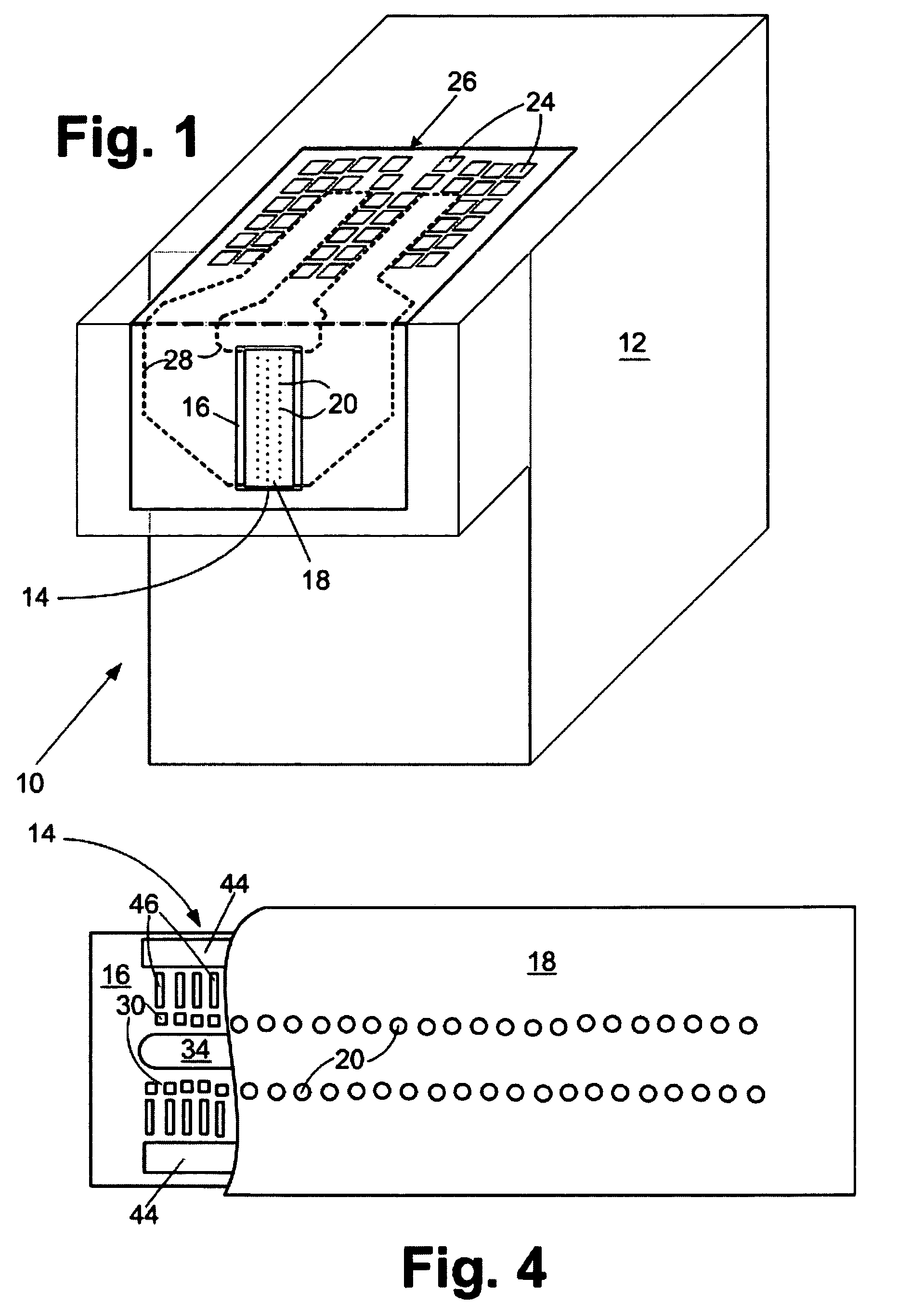
[0014]With reference to FIG. 1, a fluid cartridge 10 for a micro-fluid ejection device is illustrated. The cartridge 10 includes a cartridge body 12 for supplying a fluid to a fluid ejection head 14. The fluid may be contained in a storage area in the cartridge body 12 or may be supplied from a remote source to the cartridge body.

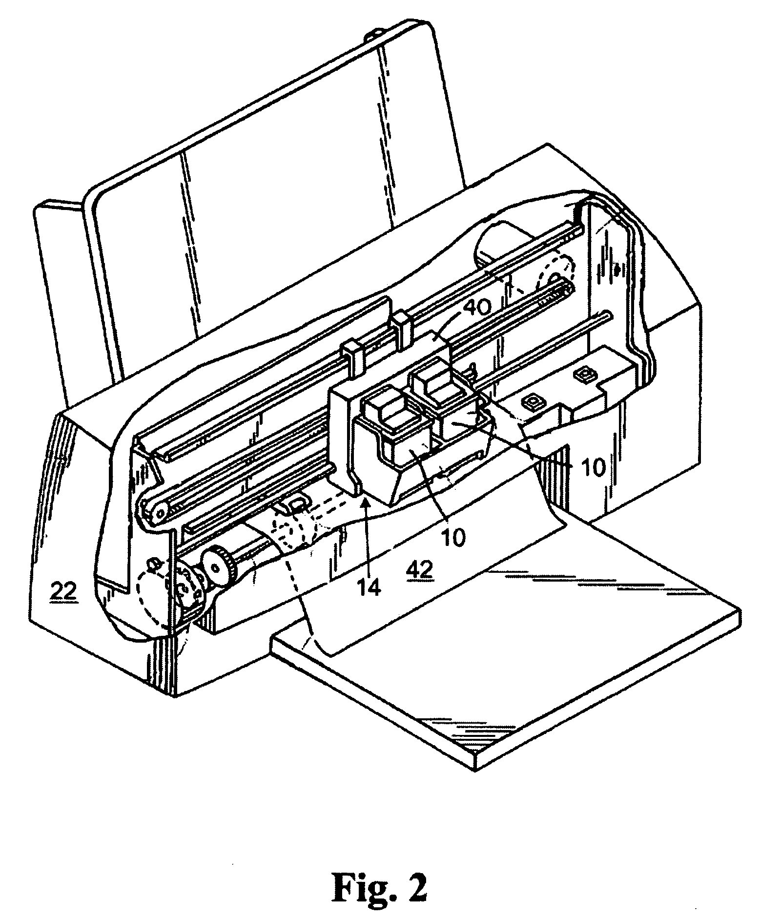
[0015]The fluid ejection head 14 includes a semiconductor substrate 16 and a nozzle plate 18 containing nozzle holes 20. In one embodiment of the present invention, it is preferred that the cartridge be removably attached to a micro-fluid ejection device such as an ink jet printer 22 (FIG. 2). Accordingly, electrical contacts 24 are provided on a flexible circuit 26 for electrical connection to the micro-fluid ejection device. The flexible circuit 26 includes electrical traces 28 that are connected to the substrate 16 of the fluid ejection head 14.

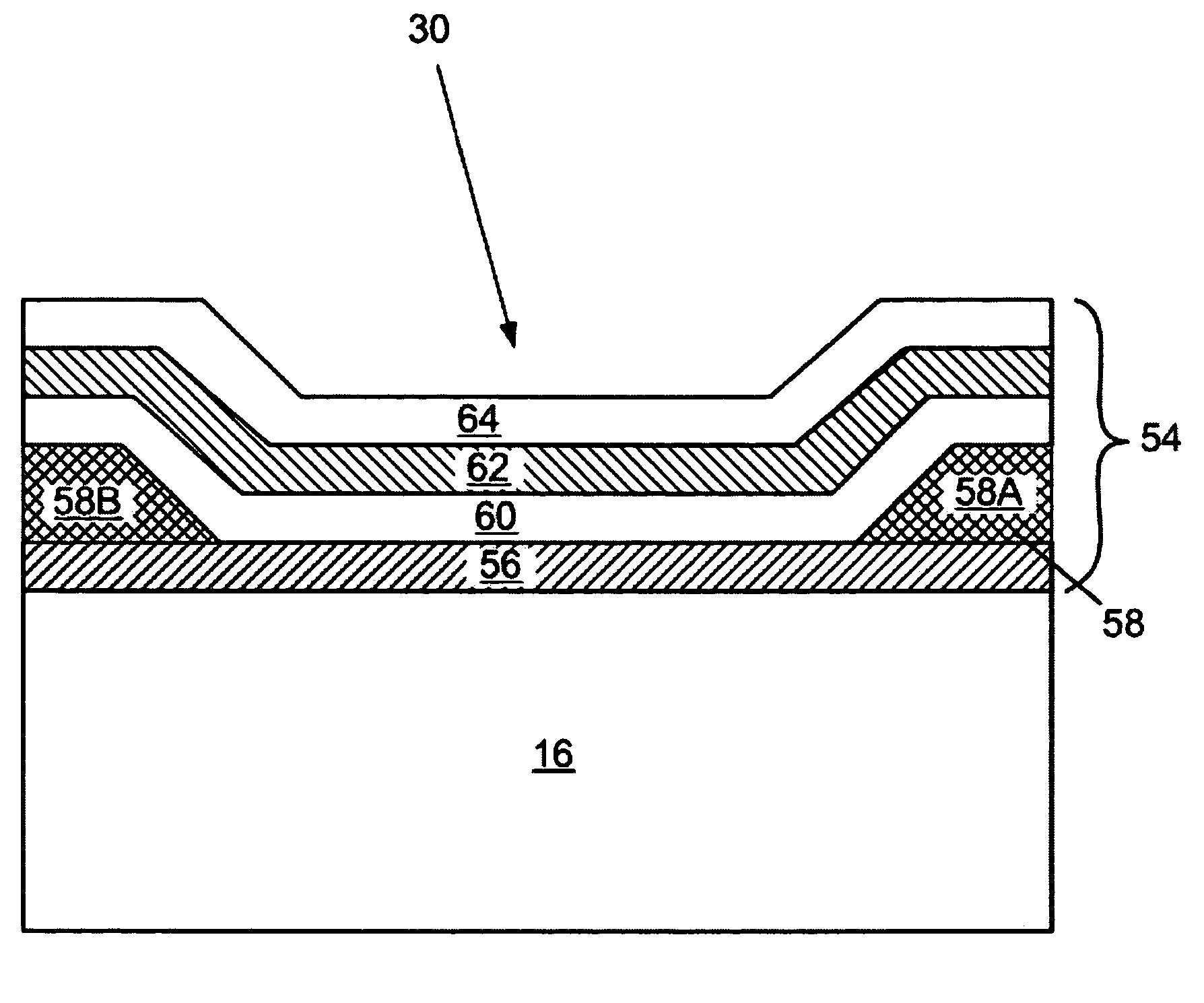
[0016]An enlarged cross-sectional view, not to scale, of a portion of the fluid ejection head 14 is illustrated...


PUM

PropertyMeasurementUnit
sheet resistanceaaaaaaaaaa
temperatureaaaaaaaaaa
thicknessaaaaaaaaaa

Abstract

A semiconductor substrate for a micro-fluid ejection head. The substrate includes a plurality of fluid ejection actuators disposed on the substrate. Each of the fluid ejection actuators includes a thin heater stack comprising a thin film heater and one or more protective layers adjacent the heater. The thin film heater is made of a tantalum-aluminum-nitride thin film material having a nano-crystalline structure consisting essentially of AlN, TaN, and TaAl alloys, and has a sheet resistance ranging from about 30 to about 100 ohms per square. The thin film material contains from about 30 to about 70 atomic % tantalum, from about 10 to about 40 atomic % aluminum and from about 5 to about 30 atomic % nitrogen.

Description

FIELD OF THE INVENTION[0001]The invention relates to micro-fluid ejection devices and in particular to ejection heads for ejection devices containing high resistance heater films.BACKGROUND OF THE INVENTION[0002]Micro-fluid ejection devices such as ink jet printers continue to experience wide acceptance as economical replacements for laser printers. Micro-fluid ejection devices also are finding wide application in other fields such as in the medical, chemical, and mechanical fields. As the capabilities of micro-fluid ejection devices are increased to provide higher ejection rates, the ejection heads, which are the primary components of micro-fluid devices, continue to evolve and become more complex. As the complexity of the ejection heads increases, so does the cost for producing ejection heads. Nevertheless, there continues to be a need for micro-fluid ejection devices having enhanced capabilities including increased quality and higher throughput rates. Competitive pressure on prin...

Claims


Application Information

Patent Timeline
Patent Type & Authority Patents(United States)
IPC IPC(8): B41J2/05B41J2/14
CPCB41J2/14129B41J2202/03Y10T29/49401Y10T29/49163Y10T29/49099Y10T29/49098Y10T29/49082Y10T29/49346
Inventor BELL, BYRON V.CORNELL, ROBERT W.GUAN, YIMINPARISH, GEORGE K.
Owner SLINGSHOT PRINTING LLC
Why Eureka
Try Eureka