Temperature sensing system for temperature measurement in a high radio frequency environment

a high-radio frequency environment and temperature sensing technology, applied in the field of temperature sensing systems, can solve the problems of non-contact temperature sensors that tend to respond more quickly to temperature changes, are more expensive, and have less accuracy differences between contact and non-contact temperature sensors

Inactive Publication Date: 2006-07-25
LAM RES CORP
View PDF20 Cites 38 Cited by
  • Summary
  • Abstract
  • Description
  • Claims
  • Application Information

AI Technical Summary

Benefits of technology

[0010]The present invention relates to an embedded thermocouple sensor for measuring temperatures of articles or areas even in a high radio frequency environment. The embedded thermocouple sensor is particularly well suited for temperature measurements within semiconductor processing chambers.

Problems solved by technology

In effect, the contact temperature sensors measure their own temperature and tend to be slow in responding to temperature changes.
The non-contact temperature sensors tend to respond more quickly than contact temperature sensors, but are more expensive.
There are also accuracy differences between contact and non-contact temperature sensors.
In situations in which the temperature sensing must occur in the presence of significant amounts of radio frequency (RF) interference, the temperature sensing is made more difficult.
Specifically, the RF noise tends to interfere with electrical signals that represent the temperature measurement.
Hence, temperature measurement is often not possible because the electrical signals normally used to represent the temperature measurement are overwhelmed by the RF interference.
For contact temperature measurement, there are various ways to measure temperature, e.g., thermistors, resistance temperature devices (RTD), thermocouples, platinum resistance bulbs, bulk silicon devices, and active solid state devices, but temperature sensing in an environment having significant RF interference remains technologically challenging as electrical temperature sensors pick up the RF interference.
Another problem with contact temperature measurement is that the temperature sensors can perturb the RF tuning and operation of the discharge in a semiconductor processing chamber by virtue of their impedence to ground, particularly if arching occurs.
If arching occurs, the sensor and measurement circuit may be damaged or destroyed.
With the RF tuning perturbed, the processing within the semiconductor processing chamber is no longer reliable.
Some infrared techniques, such as infrared thermocouples, can remain unaffected by RF interference, however, these temperature sensors are limited to use in low temperature environments.
Even if these optical approaches are able to provide optical isolation that mitigates RF interference, there are some problems with these approaches.
One problem is that the optical approaches must deal with the optical interference from the glow discharge internal to the processing chamber.
More particularly, in the case of semiconductor manufacturing equipment, the temperature of various components within the processing chamber affects the processing performed by the semiconductor manufacturing equipment.
For example, in the case of etching, the etch process should occur within a predetermined temperature range and when the temperature exceeds the predetermined temperature range, the etching reactions will be altered, thereby causing etch process drift.
More seriously, if a processing chamber is overheated for an extended length of time, but not noticed by the operators because of lack of temperature monitoring, the process chamber can be seriously damaged.
Another problem with these optical approaches is that the cost for such temperature monitoring systems is expensive, since a spectrometer or other sophisticated electro-optic instruments may be required.

Method used


Image

  • Temperature sensing system for temperature measurement in a high radio frequency environment
  • Temperature sensing system for temperature measurement in a high radio frequency environment
  • Temperature sensing system for temperature measurement in a high radio frequency environment

Examples


Embodiment Construction

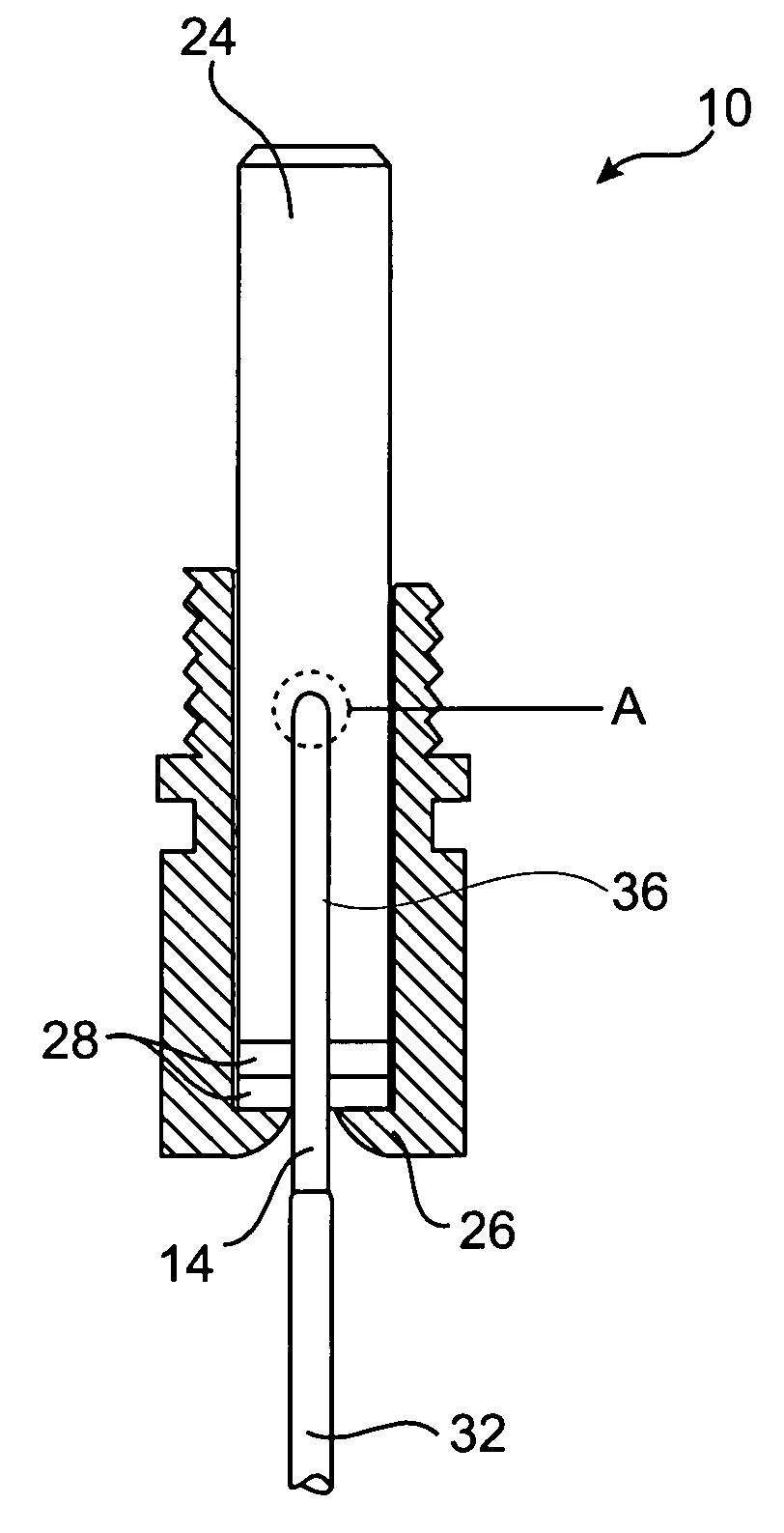
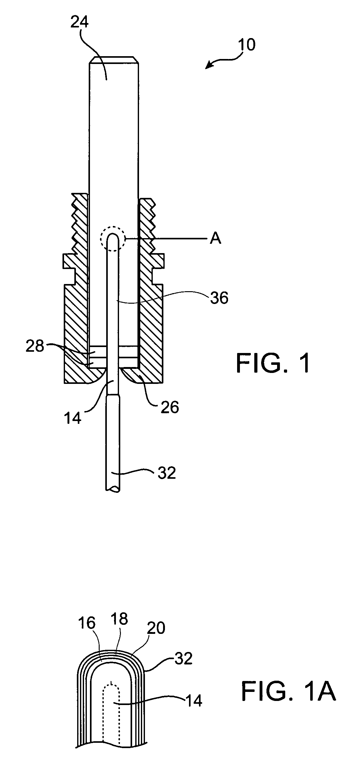
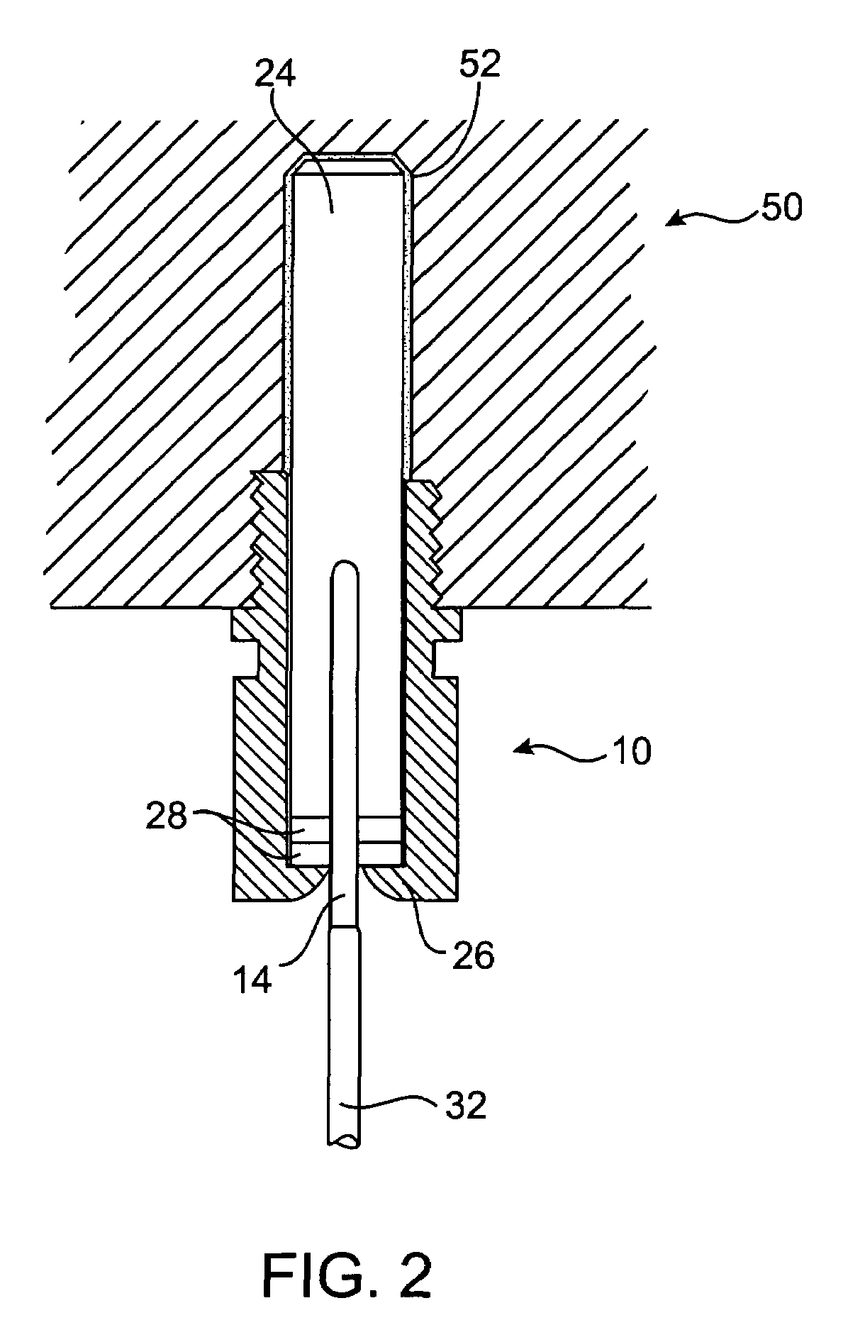
[0024]The invention relates to a temperature sensing system that measures temperatures of articles or areas using an electrical contact sensor. The temperature sensing system of the present invention is able to operate effectively and reproducibly even in a high radio frequency environment.

[0025]The temperature sensing system includes a contact sensor having an RF insulating tip. The temperature sensing system is placed in contact with an article or area for monitoring its temperature. The contact sensor with the insulating tip is useful in noisy environments to shield out external fields, such as RF electromagnetic fields and other noise, so that the contact sensor can operate more accurately and so that RF filtering requirements for down stream instrumentation are significantly reduced. The contact sensor used in the temperature sensing system of the present invention is described below as a thermocouple. However, other types of electrical contact sensors may also be used includin...


PUM

PropertyMeasurementUnit
lengthaaaaaaaaaa
frequenciesaaaaaaaaaa
lengthaaaaaaaaaa

Abstract

A temperature sensing system incorporates a contact temperature sensor probe for measuring the temperature of articles. The probe is able to operate effectively even in high radio frequency environments such as those present within radio frequency excited plasma processing chambers. The temperature sensing system includes a contact temperature sensor, such as a thermocouple, surrounded by a shielding sheath of a material such as aluminum which is clad with one or more layers of a cladding material. A tip insulator is provided surrounding the sheath for providing RF insulation and thermal coupling. An RF insulating and thermal insulating mounting member is connected to the tip insulator for mounting the probe on an article to be measured.

Description

CROSS REFERENCE TO RELATED APPLICATIONS[0001]This application claims priority to U.S. Provisional Patent Application Ser. No. 60 / 338,033, filed on Nov. 13, 2001, which is hereby incorporated by reference in its entirety.FIELD OF THE INVENTION[0002]The invention relates to a temperature sensing system, and more particularly the invention relates to a temperature sensing system for temperature measurement in a high radio frequency environment.DESCRIPTION OF THE RELATED ART[0003]Temperature sensing using temperature senors has in the past been performed in many ways for many purposes. In general, temperature measurement can be divided into two categories: contact temperature measurement and non-contact temperature measurement. In the contact category, temperature sensing devices contact a surface whose temperature is to be measured. In effect, the contact temperature sensors measure their own temperature and tend to be slow in responding to temperature changes. On the other hand, in th...

Claims


Application Information

Patent Timeline
Patent Type & Authority Patents(United States)
IPC IPC(8): G01K7/00G01K1/08G01K13/00
CPCG01K1/08
Inventor BENJAMIN, NEILROSS, CHARLESBABB, RORY
Owner LAM RES CORP
Why Eureka
Try Eureka