Cyclical deposition of refractory metal silicon nitride

Inactive Publication Date: 2006-07-25
APPLIED MATERIALS INC
View PDF204 Cites 115 Cited by
  • Summary
  • Abstract
  • Description
  • Claims
  • Application Information

AI Technical Summary

Benefits of technology

[0014]Embodiments of the invention relate to an apparatus and method of cyclical layer deposition utilizing three or more precursors. In one embodiment, the method includes introducing a pulse of a nitrogen-containing precursor and providing at least one cycle of precursors to form a ternary material layer. The nitrogen-containing precursor is introduced first to prevent diffusion of a refractory metal-containing precursor and a silicon-containing precursor

Problems solved by technology

Low dielectric-constant materials are often soft and porous, and adhere poorly to adjacent materials.
However, such deposition methods are performed at higher temperatures which may not be desirable for some applications, and have trouble controlling the composition of the barrier/adhesion layer, such as the ratio of the materials incorporated.
In addition, traditional deposition processes, such as physical vapor deposition (PVD) and chemical vapor deposition (CVD), have difficulty in filling high aspect ratio features and often result in poor step coverage, poor conformality, and bypr

Method used


Image

  • Cyclical deposition of refractory metal silicon nitride
  • Cyclical deposition of refractory metal silicon nitride
  • Cyclical deposition of refractory metal silicon nitride

Examples


example a

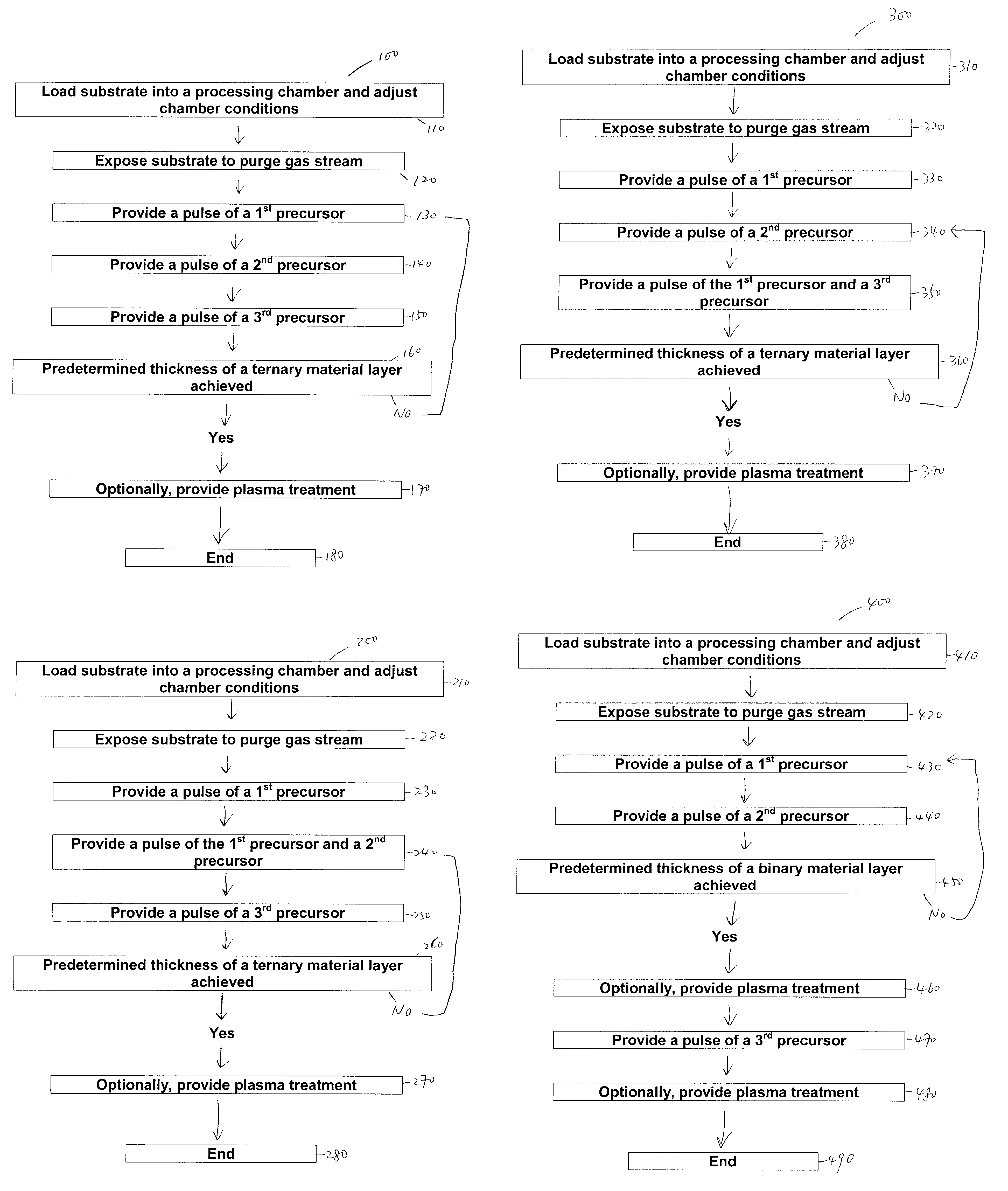
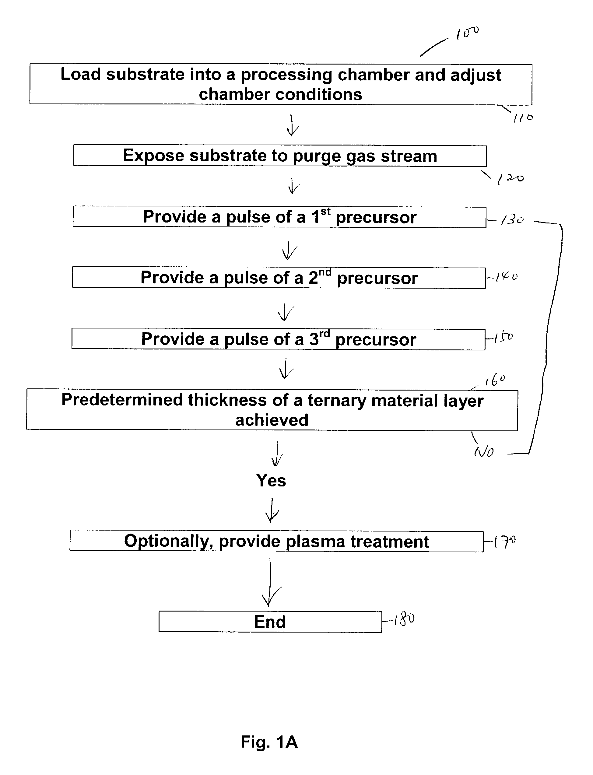
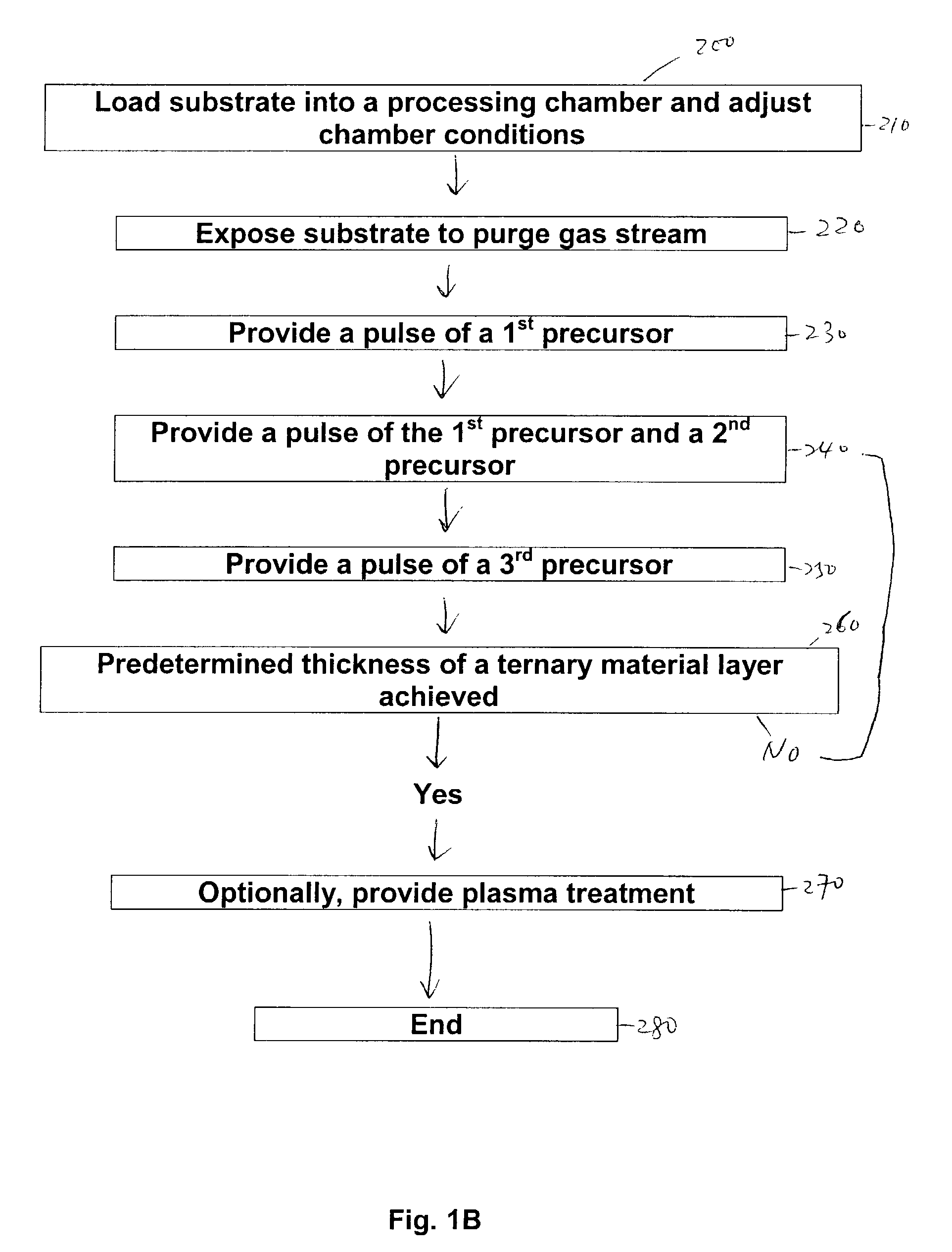
[0101]FIG. 4 is a comparison of the results of two flow sequences similar to the flow sequence 100 in FIG. 1A where three precursors are sequentially introduced into the flow sequence to form a tantalum silicon nitride layer. The difference between these two flow sequences was the order of the second and the third precursors. The precursors in these two flow sequences were ammonia used as the first precursor, and silane and pentakis (ethylmethylamino) tantalum (PEMAT) used as the second and the third precursors or vice versa. The two flow sequences were performed at about 215° C. chamber temperature. As a test, delivery of the ammonia was at a flow rate of about 500 sccm and a deposition pressure of about 10 Torr for a pulse of about 10 second. Delivery of the PEMAT was at a flow rate of about 200 sccm for a pulse of about 10 second, with an argon carrier gas of a deposition pressure of about 5 Torr. Delivery of the silane was at a flow rate of about 50 sccm for a pulse of about 10 ...

example b

[0104]The results performed by a flow sequence similar to the flow sequence 400 in FIG. 1D form a titanium nitride layer prior to the formation of a titanium silicon nitride layer are summarized below. The precursors used were ammonia as the first precursor, tetrakis (diethylamino) titanium (TDMAT) as the second precursor, and silane as the third precursor.

[0105]In FIG. 5A, the flow sequence is performed at various temperatures between about 150° C. and about 350° C. Decomposition of the titanium nitride layer as measured by X-ray fluorescence (XRF) counts in kilocounts per second (kcps) is shown as a function of the temperature of the heater for heating up the chamber. The results suggest that deposition is better at a temperature of about 250° C. or less because decomposition of the TDMAT precursor as indicated by the X-ray fluorescence (XRF) counts starts at a temperature of about 250° C. or more. The decomposition is not as severe when a longer duration of a pulse of a purge gas...


PUM

PropertyMeasurementUnit
Refractoryaaaaaaaaaa

Abstract

Embodiments of the invention relate to an apparatus and method of cyclical layer deposition utilizing three or more precursors. In one embodiment, the method includes providing at least one cycle of precursors to form a ternary material layer. Providing at least one cycle of precursors includes introducing a pulse of a first precursor, introducing a pulse of a second precursor, and introducing a pulse of a third precursor, wherein the pulses of two of the three precursors are introduced simultaneously or sequentially. In another embodiment, the method includes introducing a pulse of a first precursor, introducing a pulse of a second precursor, repeating the introduction of the first and the second precursors at least one time to form a binary material layer on the substrate surface, and introducing a pulse of a third precursor to form the ternary material layer.

Description

CROSS-REFERENCE TO RELATED APPLICATIONS[0001]This application claims benefit of U.S. provisional patent application Ser. No. 60 / 337,646, entitled, “Deposition of Tantalum Silicon Nitride Using Atomic Layer Deposition for Copper Metallization”, which was filed Dec. 4, 2001 and is incorporated herein by reference.BACKGROUND OF THE INVENTION[0002]1. Field of the Invention[0003]Embodiments of the invention generally relate to deposition of a semi-conductive layer onto a substrate. More specifically, the invention relates to a method of depositing a refractory metal layer using a cyclical deposition technique.[0004]2. Description of the Related Art[0005]The requirements of sub-quarter micron semiconductor devices with their VSLI or USLI integration necessitate using various layers, e.g., conductive layers and insulating layers. Typically, conductive layers are interconnected through features such as horizontal lines and vertical contact holes, vias, trenches, or openings in the insulatin...

Claims


Application Information

Patent Timeline
IPC IPC(8): C23C16/34C23C16/44C23C16/455H01L21/285H01L21/768
CPCC23C16/45531C23C16/34H01L21/28562H01L21/76843
Inventor CHUNG, HUACHEN, LINGCHIN, BARRY L.
Owner APPLIED MATERIALS INC
Why Eureka
Try Eureka