Switching device for controlling large amount of current

a technology of switching device and current, which is applied in the direction of electric devices, transportation and packaging, and associations of printed circuit non-printed electric components, etc., can solve the problems of complex structure of power switching device, high manufacturing cost, and high circuit impedance, so as to reduce heat generation, facilitate position, and shorten the length of the leads connecting drains and sources

Inactive Publication Date: 2006-07-25
DENSO CORP
View PDF5 Cites 45 Cited by
  • Summary
  • Abstract
  • Description
  • Claims
  • Application Information

AI Technical Summary

Benefits of technology

[0011]A step, against which a lower fringe of the insulation sheet abuts, may be formed on the sloped mounting surface to easily position the insulation sheet on the sloped mounting surface. The heat-sink block may be formed to includes a pair of sloped mounting surfaces to mount plural switching elements thereon. In this case, the connecting leads of the switching elements mounted on one surface face the connecting leads of the switching elements mounted on the other surface. Preferably, drain leads (or source leads) of the switching elements mounted on one surface are aligned in line with source leads (or drain leads) of the

Problems solved by technology

Accordingly, the structure of the power-switching device becomes complex and its manufacturing cost becomes high.
Further, though the metallic substrate has a high heat-dissipation abilit

Method used


Image

  • Switching device for controlling large amount of current
  • Switching device for controlling large amount of current
  • Switching device for controlling large amount of current

Examples


Embodiment Construction

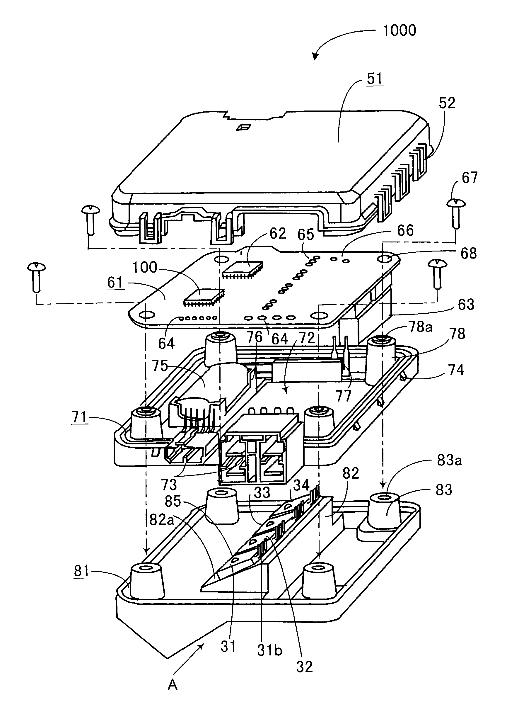
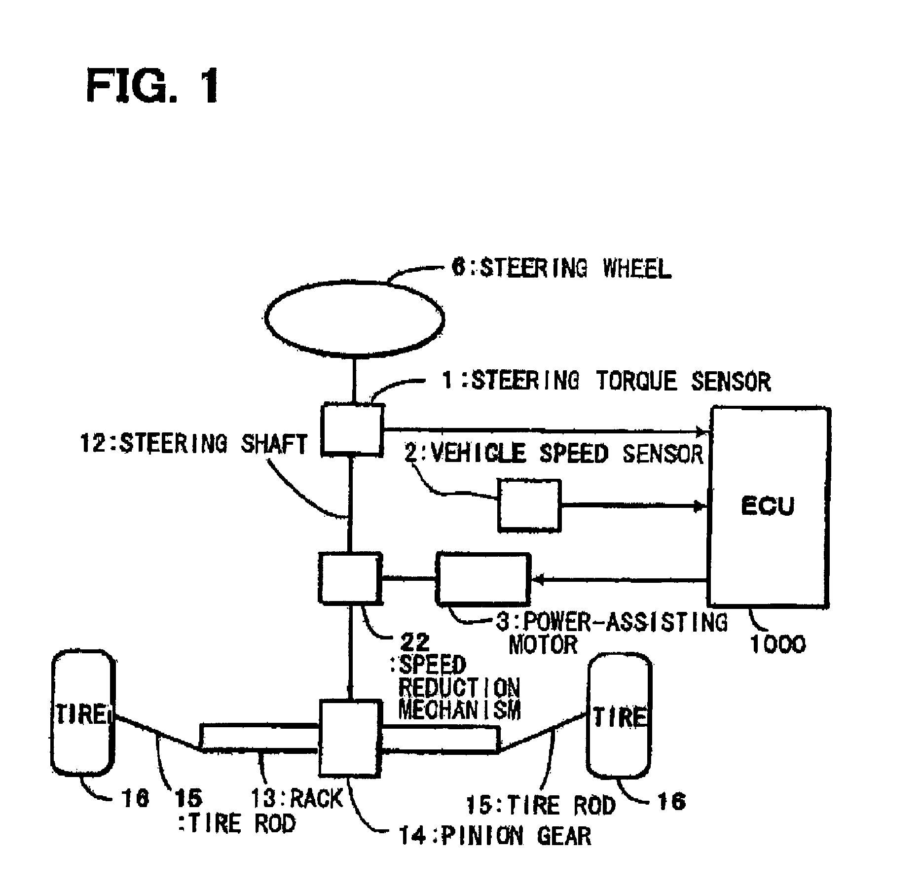
[0023]A preferred embodiment of the present invention will be described with reference to FIGS. 1–4B. FIG. 1 shows an entire structure of a motor-assisted steering system, in which a switching device according to the present invention is used. The switching device is included in an electronic control unit (referred to as an ECU) 1000. A steering shaft 12 is connected to a steering wheel 6 that is driven by a driver. A pinion gear 14 that engages with a rack 13 is connected to the steering shaft 12. A pair of tires 16 is connected to the rack 13 through a pair of tie-rods 15. Thus, the pair of tires 16 is steered in response to rotation of the steering wheel 6.

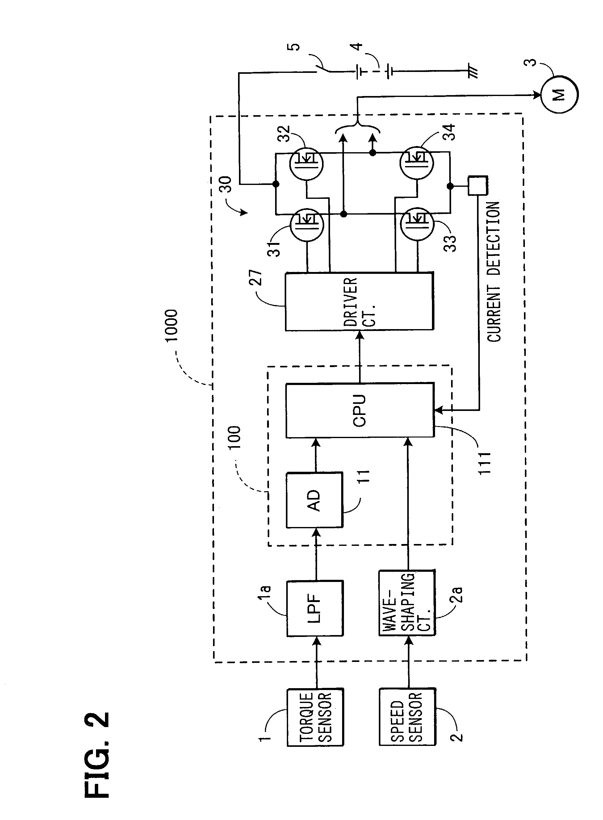
[0024]A steering torque sensor 1 is coupled to the steering shaft 12, and the steering torque sensor 1 outputs electrical signals representing a steering torque generated by rotating the steering wheel 6. A power-assisting motor 3 (a direct current motor) is connected to the steering shaft 12 through a speed reduction mechanism...


PUM


Abstract

A switching device for controlling a large amount of current includes a circuit board carrying electronic components thereon, a power-switching element electrically connected to the circuit board, and a housing disposed underneath the circuit board and containing the power-switching element therein. The housing made of a heat-conductive material includes a heat-sink block having a sloped surface on which the power-switching element is mounted. Connecting leads extending from the power-switching element are positioned at an upper portion of the sloped surface which is close to the circuit board. In this manner, the length of connecting leads is shortened and heat and noises generated therein are suppressed.

Description

CROSS-REFERENCE TO RELATED APPLICATION[0001]This application is based upon and claims benefit of priority of Japanese Patent Application No. 2002-115252 filed on Apr. 17, 2002, the content of which is incorporated herein by reference.BACKGROUND OF THE INVENTION[0002]1. Field of the Invention[0003]The present invention relates to a switching device that controls a large amount of current, the switching device including a power-switching element such as a switching transistor, and more particularly to such a switching device used for controlling operation of a motor-assisted steering device.[0004]2. Description of Related Art[0005]An example of a conventional power-switching device is shown in FIG. 7. A switching element 131, such as a power-MOS-FET or an IGBT, is mounted on a heat-sink block 181 having a flat mounting surface 182. A connecting lead 131b led out from the switching element 131 is electrically connected to a printed circuit board 161 by soldering. Heat generated in the ...

Claims


Application Information

Patent Timeline
IPC IPC(8): H05K7/20B62D5/04H05K1/02H05K1/18H05K7/14
CPCH05K1/0203H05K7/1432H05K2201/1056H05K2201/10484H05K2201/10166B62D5/0406H05K7/209H05K7/14322
Inventor KAWATA, HIROYUKI
Owner DENSO CORP
Why Eureka
Try Eureka