Apparatus and method for pressure-compensated telemetry and power generation in a borehole

a technology of pressure compensation and power generation, which is applied in the direction of borehole/well accessories, surveying, drilling pipes, etc., can solve the problems of increasing the cost of downhole power supply, increasing the cost of downhole alternator failures, and a significant percentage of the failures and maintenance costs of downhole alternators. to achieve the effect of relieving excess pressur

Inactive Publication Date: 2006-08-01
SCHLUMBERGER TECH CORP
View PDF19 Cites 32 Cited by
  • Summary
  • Abstract
  • Description
  • Claims
  • Application Information

AI Technical Summary

Benefits of technology

[0014]Accordingly, a portion of the drilling fluid flowing through the drill collar when the stator is secured therein is conducted through the inlet to apply a first nominal pressure against the rotary seal. A portion of the flowing drilling fluid is further conducted through the port to apply a nominal pressure against the movable barrier that urges compensating fluid in the first compensating chamber to be conducted through the gap so as to apply a second nominal pressure against the rotary seal opposing the first nominal pressure. The second nominal pressure is at least as great as the first nominal pressure so as to compensate the pressure of drilling fluid in the inlet and prevent drilling fluid from entering the gap. Such compensation is preferably achieved by positioning the port upstream of the inlet, so as to ensure that drilling fluid conducted through the port has a greater nominal pressure than the drilling fluid conducted through the inlet.
[0019]The inventive apparatus preferably further includes a compressible element disposed in the first compensating chamber for reducing the risk of damage to the apparatus should the apparatus be subjected to freezing temperatures. The compressible element is, in one embodiment, a metal bellows that is partially filled with a fluid for preventing over-pressuring of the compressible element.
[0021]The inventive method preferably further includes the step of relieving excess pressure in the isolated compensating fluid that may occur due to thermal expansion.

Problems solved by technology

Since it is not feasible to run a power supply cable from the surface through the drill string to the sensors or the telemetry means, electrical power must be obtained downhole.
The face of a typical rotary seal has to be lubricated by something other than the drilling fluid, since the drilling fluid contains erosive particles that will quickly ruin the rotary seal.
For drilling efficiency, this piston is required to move a significant distance over time, which makes the spring and the chamber longer and bulkier than they might otherwise have to be.
Accordingly, the compensating piston / spring assembly tends to make the downhole provision of power expensive.
Furthermore, experience in the art has proven that a significant percentage of the failures and maintenance costs associated with downhole alternators are due to the extended length of the piston / spring oil reservoir pressure-compensation system.
Still further, such a piston / spring configuration is, in many applications, an inefficient method of providing the necessary pressure rise needed to match the mud pressure.

Method used


Image

  • Apparatus and method for pressure-compensated telemetry and power generation in a borehole
  • Apparatus and method for pressure-compensated telemetry and power generation in a borehole
  • Apparatus and method for pressure-compensated telemetry and power generation in a borehole

Examples


Embodiment Construction

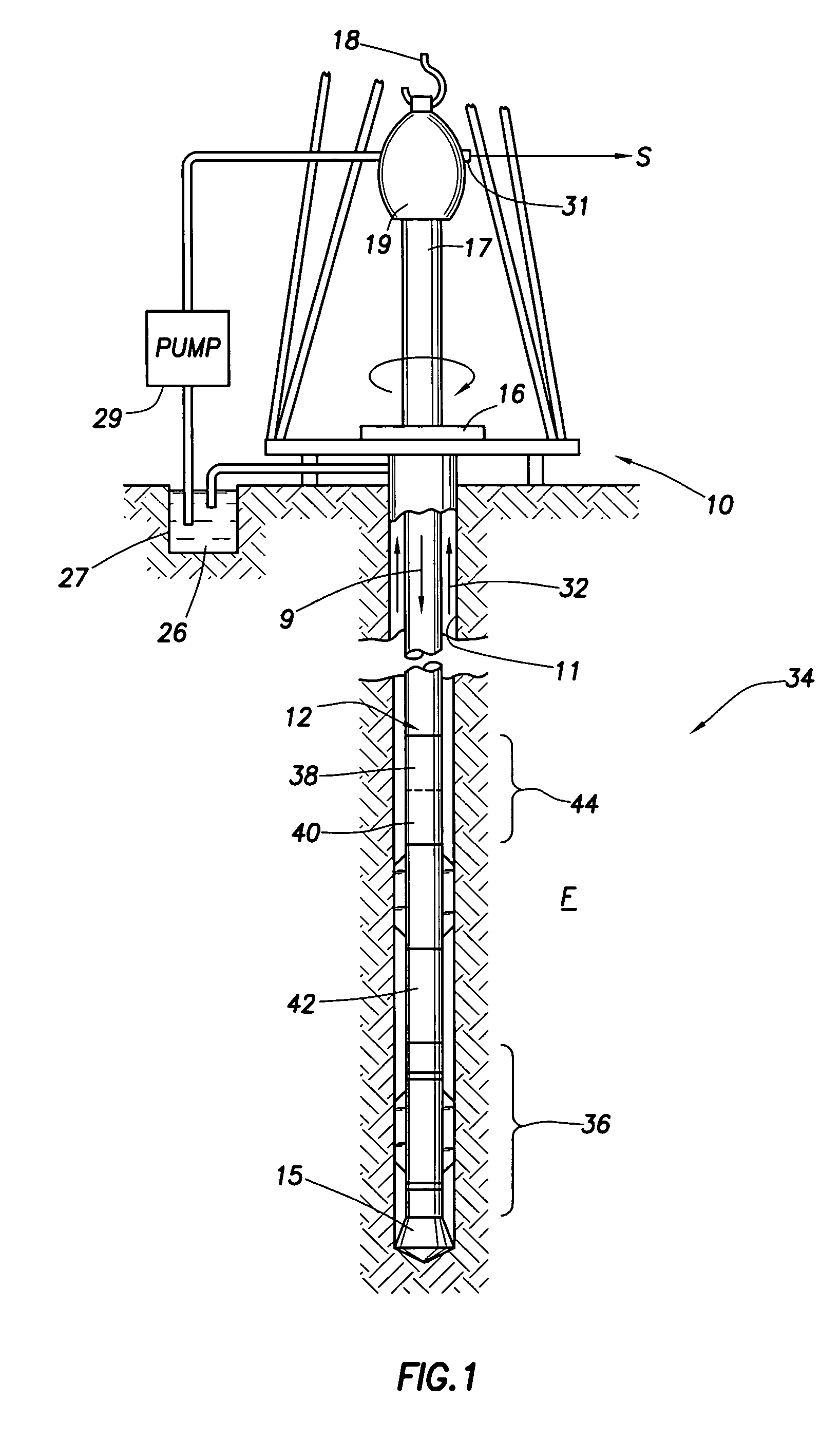
[0031]FIG. 1 illustrates a convention drilling rig and drill string in which the present invention can be utilized to advantage. A land-based platform and derrick assembly 10 are positioned over a borehole 11 penetrating a subsurface formation F. In the illustrated embodiment, the borehole 11 is formed by rotary drilling in a manner that is well known. Those of ordinary skill in the art given the benefit of this disclosure will appreciate, however, that the present invention also finds application in drilling applications other than conventional rotary drilling (e.g., mud-motor based directional drilling), and is not limited to land-based rigs.

[0032]A drill string 12 is suspended within the borehole 11 and includes a drill bit 15 at its lower end. The drill string 12 is rotated by a rotary table 16, energized by means not shown, which engages a kelly 17 at the upper end of the drill string. The drill string 12 is suspended from a hook 18, attached to a traveling block (also not show...


PUM


Abstract

An apparatus and related method are useful for compensating the pressure of drilling fluid in a drill collar disposed in a borehole. The apparatus includes a stator adapted for being secured within the drill collar against rotation relative to the drill collar, and a shaft rotatably carried within the stator so as to define a fluid-conducting annular gap between the shaft and the stator. The shaft has a fluid-conducting channel extending axially therethrough. A rotor is secured about the shaft for rotation therewith. A portion of the rotor is disposed adjacent a portion of the stator so as to define an inlet between the rotor and stator portions through which drilling fluid in the drill collar will be conducted. The rotor portion further cooperates with the stator and the shaft to define a first annular cavity that fluidly communicates with the gap and the inlet. A rotary seal is disposed in the first cavity for isolating the gap from the inlet. Either the rotor, the shaft, or a combination thereof, are equipped with a first compensating chamber for holding a compensating fluid. The first compensating chamber fluidly communicates with the gap. A movable barrier is disposed in the first compensating chamber for isolating the compensating fluid. At least one port extends through the rotor for communicating drilling fluid pressure to the compensating fluid via the movable barrier.

Description

BACKGROUND OF THE INVENTION[0001]1. Field of the Invention[0002]The present invention relates to downhole tools used in oil and gas drilling operations, and more particularly, to telemetry and power-generating means for measurement-while-drilling (MWD) tools and processes used in such operations.[0003]2. Background of the Related Art[0004]The drilling of oil and gas wells typically involves the use of several different measurement and telemetry systems to provide data regarding the subsurface formation penetrated by a borehole, and data regarding the state of various drilling mechanics during the drilling process. In measurement-while-drilling (MWD) tools, data is acquired by sensors located in the drill string near the bit. This data is either stored in downhole memory or transmitted to the surface using a telemetry means, such as mud flow telemetry devices.[0005]Both the downhole sensors and the telemetry means of the MWD tool require electrical power. Since it is not feasible to ...

Claims


Application Information

Patent Timeline
Patent Type & Authority Patents(United States)
IPC IPC(8): E21B4/04E21B17/18E21B7/00E21B41/00E21B47/12E21B47/18
CPCE21B47/182E21B41/0085E21B47/20
Inventor THORP, RICHARDEASON, RAJU
Owner SCHLUMBERGER TECH CORP
Why Eureka
Try Eureka