Seating arrangement especially adjoining an emergency exit in an aircraft passenger cabin

a seat arrangement and passenger cabin technology, applied in the direction of seat arrangement, movable seats, emergency equipment, etc., can solve the problems of difficult access to the exit and difficulty for passengers, and achieve the effect of increasing the increasing the available width of the transverse aisle, and facilitating the evacuation of the aircra

Active Publication Date: 2006-08-01
AIRBUS OPERATIONS GMBH
View PDF19 Cites 45 Cited by
  • Summary
  • Abstract
  • Description
  • Claims
  • Application Information

AI Technical Summary

Benefits of technology

[0006]In view of the above, it is an object of the invention to provide a seating arrangement in an aircraft passenger cabin that enables and facilitates a safe and rapid emergency evacuation, whereby a transverse aisle leading to an emergency exit has a sufficient width for an evacuation, while simultaneously providing the highest possible total seating density with the greatest possible total number of seat places for the passenger transport. The invention further aims to avoid or overcome the disadvantages of the prior art, and to achieve additional advantages, as apparent from the present specification. The attainment of these objects is, however, not a required limitation of the invention.
[0008]According to the invention, it is especially advantageous that the width of the transverse aisle is variable depending on the particular situation, i.e. depending on the position of the tiltable seat bottoms of the foldable passenger seats. Thus, during normal operation of the aircraft, the tiltable seat bottoms are deployed in the downwardly tilted, substantially horizontal seating position. In such a situation, there is no need for the increased width of the transverse aisle. The seats may be embodied either so that the seat bottoms remain in whichever position they have been placed manually, or so that the seat bottoms automatically tilt upwardly into the upright position. For example, each seat bottom can be spring-loaded about its pivot axis, so that it pivots upwardly under a spring bias whenever the respective seat is vacant, i.e. whenever no passenger is seated on the respective seat. Then, in an emergency evacuation situation, with the tiltable seat bottoms manually or automatically tilted upwardly, the available width of the transverse aisle is thereby increased, which enables a rapid and safe evacuation of the aircraft. Furthermore, the increased width of the transverse aisle leading to the emergency exit also makes it easier to recognize the transverse aisle and its function as an escape path.
[0009]As a result, the previously necessary fixed width of a transverse aisle (e.g. the seat row pitch or spacing between the seat rows bordering the transverse aisle) can be reduced, because the inventive arrangement provides a variable width that is smaller for an increased seating capacity in normal operation, and larger for an improved evacuation function of the transverse aisle in the event of an emergency evacuation. In this manner, the invention makes it possible to achieve an increased total passenger seating capacity while maintaining the same evacuation safety. Alternatively, the inventive arrangement can increase the evacuation safety with an increased transverse aisle width in the event of an emergency evacuation, while maintaining the same passenger seating capacity that would be provided by conventional fixed seats. Furthermore, the invention can even achieve a balance of both of the preceding advantages, namely both an increase of the total seating capacity and an increase of the width of the transverse aisle in the event of an emergency evacuation.

Problems solved by technology

A transverse aisle that is too narrow makes it difficult for passengers to recognize the emergency exit path between the successive seat rows, and also makes accessing the exit more difficult.

Method used


Image

  • Seating arrangement especially adjoining an emergency exit in an aircraft passenger cabin
  • Seating arrangement especially adjoining an emergency exit in an aircraft passenger cabin
  • Seating arrangement especially adjoining an emergency exit in an aircraft passenger cabin

Examples


Embodiment Construction

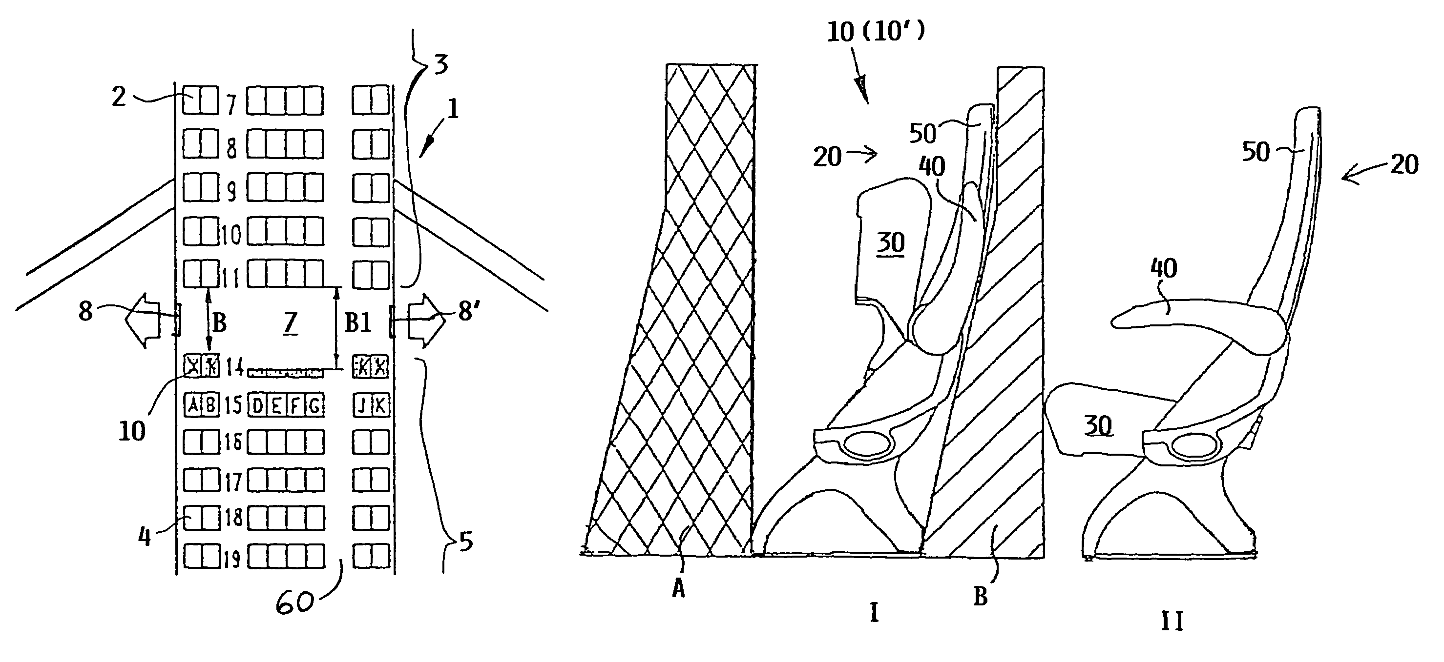
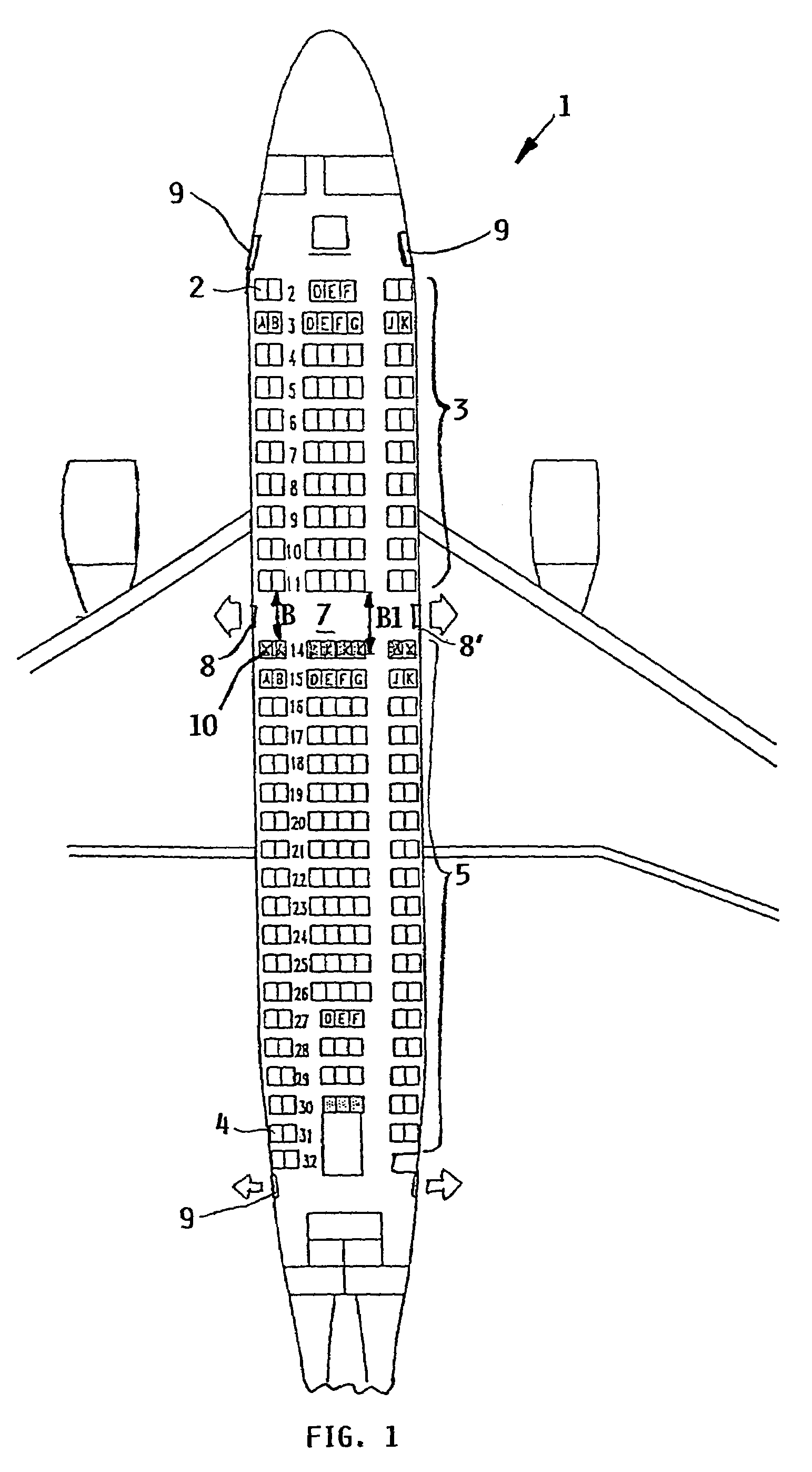
[0015]FIG. 1 schematically shows a cabin layout of a passenger transport aircraft. The passenger cabin 1 includes a business class 3 equipped with business class seat rows 2 in the forward portion of the aircraft, as well as a tourist or economy class 5 equipped with tourist or economy class seat rows 4 in the aft portion of the aircraft. As can be seen, the seat spacing or pitch in the aircraft longitudinal direction is larger for the business class seat rows 2 than the tourist class seat rows 4.

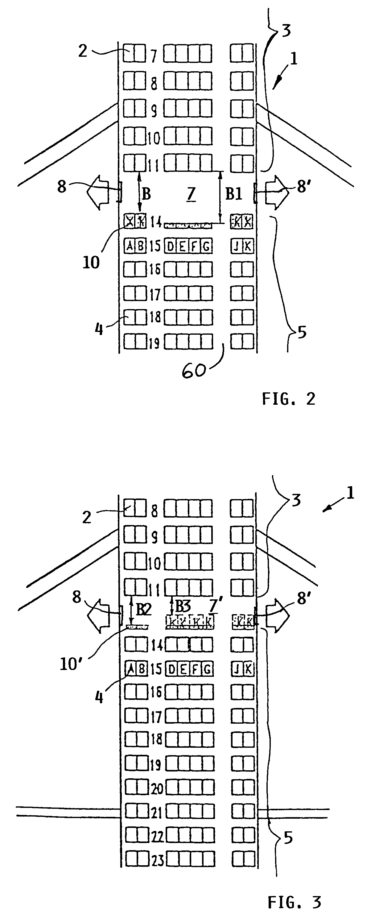
[0016]Furthermore, a transverse aisle 7 is formed between successive seat rows, in this example particularly between the business class seat rows 2 and the tourist class seat rows 4. This transverse aisle 7 extends transversely or crosswise relative to the aircraft longitudinal direction, and leads to and provides access to two emergency exits 8 and 8′ on opposite sides of the aircraft. For this purpose, the transverse aisle 7 is characterized by a rather large seat spacing or pitch (larger...


PUM


Abstract

A seating arrangement in an aircraft passenger cabin includes rows of seats, one behind another at a prescribed seat pitch. A wider transverse aisle is formed between successive seat rows at a normal exit or an emergency exit. At least one seat row bordering on and facing the transverse aisle is equipped with foldable passenger seats that each have an upwardly tiltable seat bottom and armrests. By tilting up the seat bottom and the armrests, an enlarged width of the transverse aisle is provided in the event of an emergency evacuation. In normal operation, the prescribed transverse aisle width does not need to be maintained, i.e. can be reduced, so the seat bottom and armrests are tilted down into the normal-use position for a passenger to be seated on the seat. Thereby the seat pitch of this seat row can be reduced and the total seating capacity can be increased.

Description

PRIORITY CLAIM[0001]This application is based on and claims the priority under 35 U.S.C. §119 of German Patent Application 103 07 870.3, filed on Feb. 25, 2003, the entire disclosure of which is incorporated herein by reference.FIELD OF THE INVENTION[0002]The invention relates to a seat row arrangement in a passenger cabin of a commercial passenger transport aircraft that is laid out with plural rows of passenger seats one behind another at a specified row spacing or seat pitch in the aircraft longitudinal direction. A crosswise or transverse aisle is formed by a larger row spacing between seat rows adjacent to an emergency exit to facilitate passenger access to the exit in an evacuation.BACKGROUND INFORMATION[0003]Commercial passenger transport aircraft are typically equipped with passenger seat row arrangements including different seats and different seat spacings or pitches corresponding to the class division of the passenger cabin(s), for example in first class, business class, ...

Claims


Application Information

Patent Timeline
Patent Type & Authority Patents(United States)
IPC IPC(8): B64D11/06B64D13/00B64D11/00
CPCB64D11/00B64D11/0601B64D11/06B64D25/00B64D11/0644B64D11/064
Inventor HIESENER, STEFAN
Owner AIRBUS OPERATIONS GMBH
Why Eureka
Try Eureka