
System for hydrogen generation

a hydrogen generation and hydrogen technology, applied in the direction of liquid degasification, physical/chemical process catalysts, separation processes, etc., can solve the problems of insufficient or impractical hydrogen storage methods that are currently used in many consumer applications, and liquid hydrogen is neither safe nor practical for most consumer applications

Inactive Publication Date: 2006-08-01
SILICON VALLEY BANK
View PDF21 Cites 87 Cited by
  • Summary
  • Abstract
  • Description
  • Claims
  • Application Information

AI Technical Summary

Benefits of technology

This system enhances the efficiency and economy of hydrogen generation by enabling the use of a concentrated metal hydride solution, reducing the risk of clogging, and maintaining a constant hydrogen supply, while minimizing the volume and weight of storage systems.

Problems solved by technology

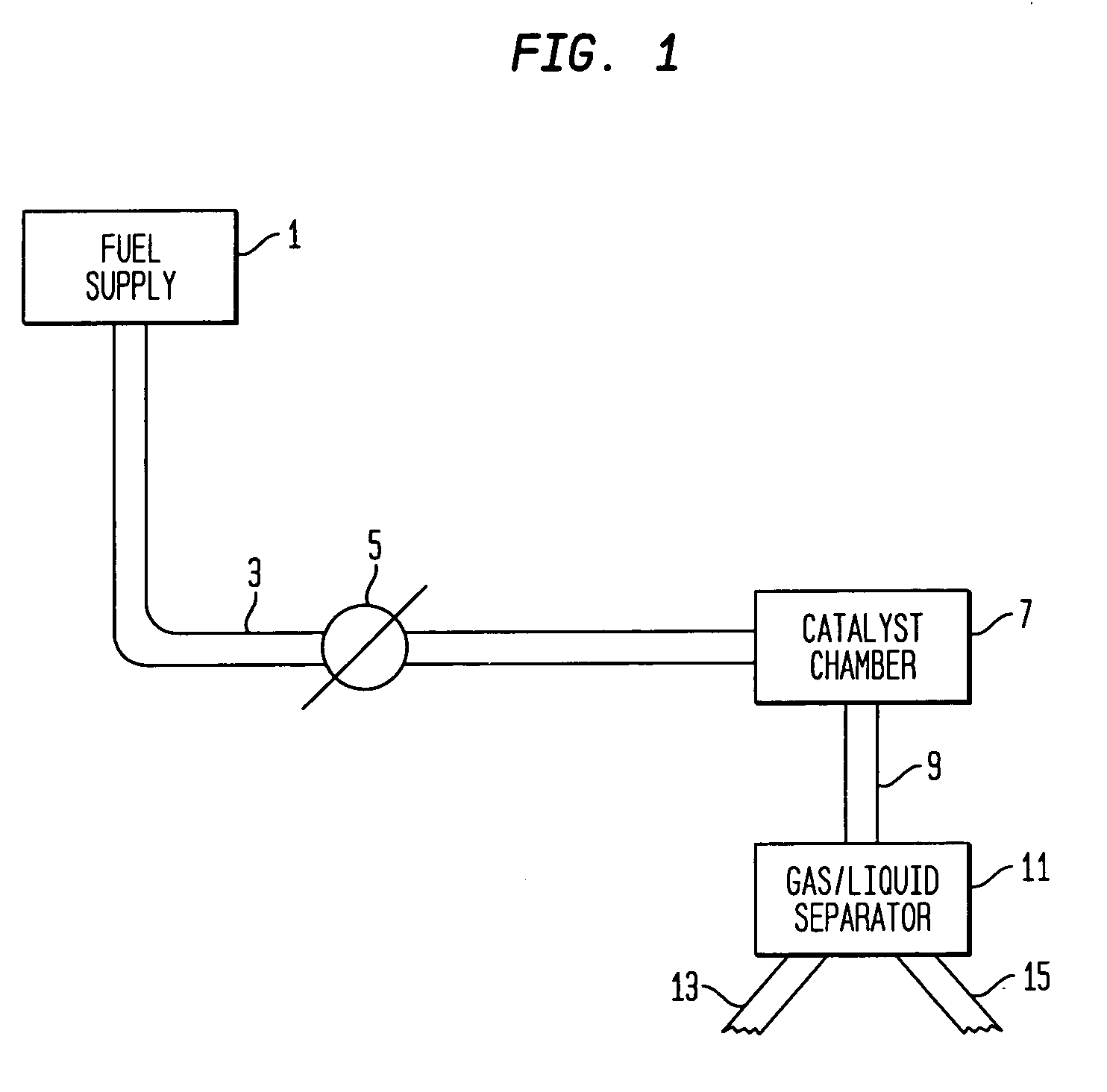
Several methods of storing hydrogen currently exist but are either inadequate or impractical for wide-spread consumer applications.
However, liquid hydrogen is neither safe nor practical for most consumer applications.

Method used


Image

  • System for hydrogen generation
  • System for hydrogen generation
  • System for hydrogen generation

Examples


example

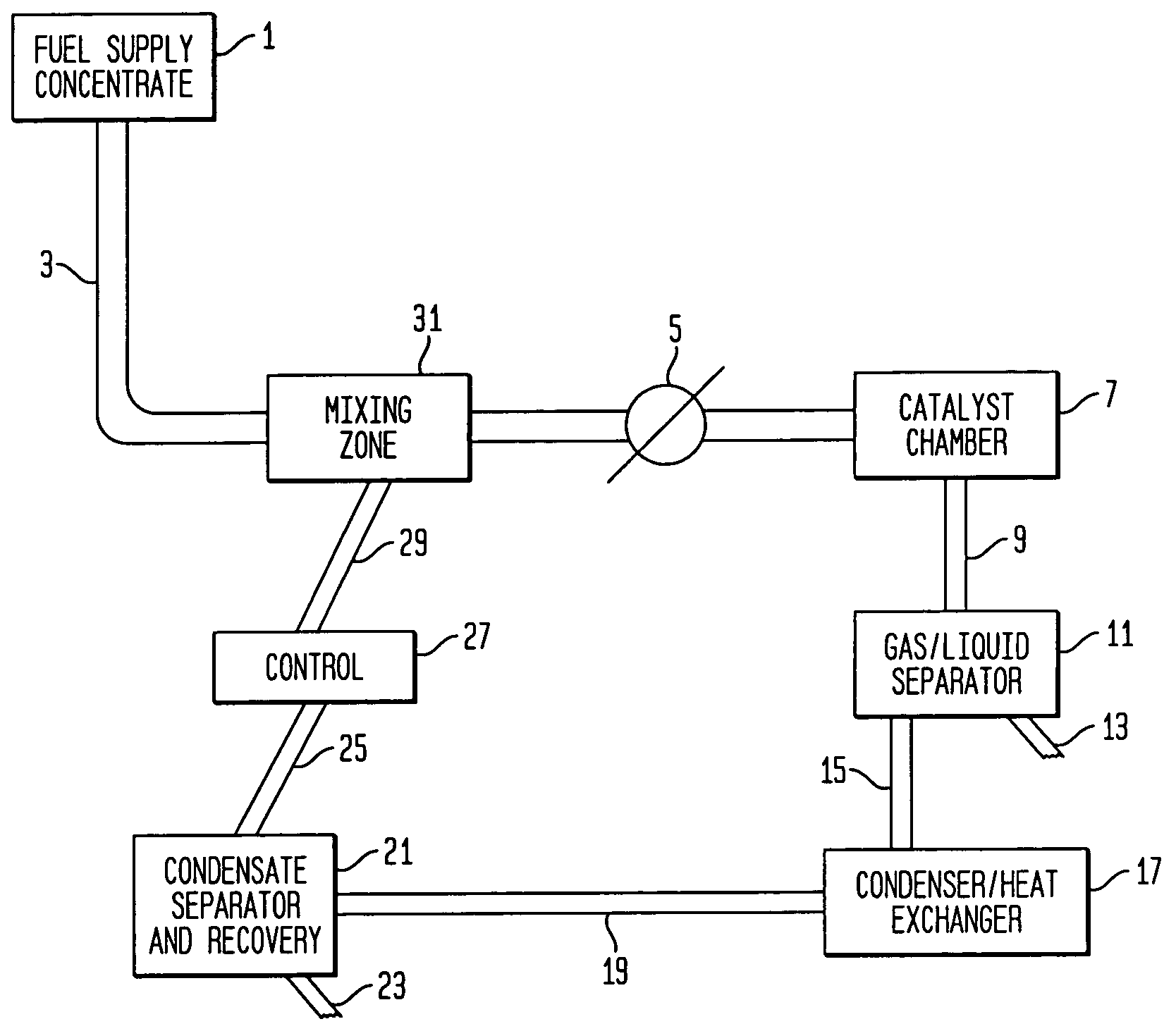
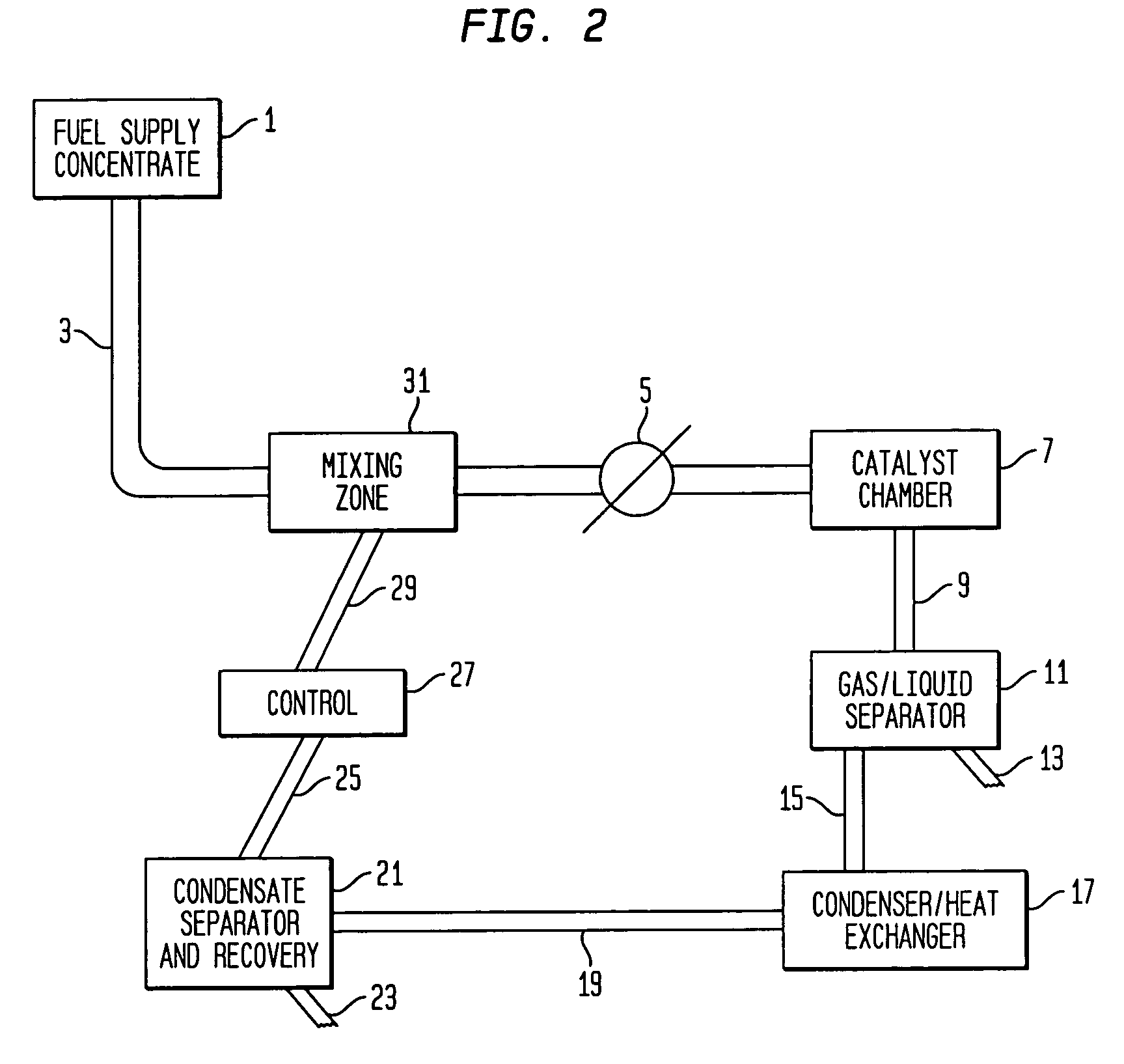
[0035]A hydrogen generation test system according to FIG. 2 was constructed to bench test the improved system of the invention. The mixing zone 5 was a static incline tube mixer consisting of tubing containing a twisted piece of metal. The fuel supply concentrate tank 1 contained a 30% aqueous solution of sodium borohydride that was passed into the system at a flow rate of approximately 850 mL / min. The condensate recycle was fed into the mixing zone 31 at a flow rate of approximately 300 mL / min. In spite of fluctuations in liquid flow rates caused by pressure variations within the system, the ratio of fuel concentrate to condensate was kept nearly constant so as to maintain a nearly constant dilute effective fuel concentration. The effective concentration of fuel solution introduced into the catalyst chamber 7 for a test run was approximately 22%. Both effective rate of hydrogen generation and conversion of the sodium borohydride fuel solution for the system were constant over the r...


PUM

PropertyMeasurementUnit
pHaaaaaaaaaa
diameteraaaaaaaaaa
diameteraaaaaaaaaa

Abstract

The present invention relates to an improvement in a system for the generation of hydrogen by contacting an aqueous solution of a metal hydride salt with a hydrogen generation catalyst. In particular, the present invention relates to the incorporation within the system of a recycle line of water condensed from the fluid product to the feed line to be contacted with the catalyst. the internal recycle line permits the use of a more concentrated solution of metal hydride as it is diluted by the recycle line prior to contact with the catalyst.

Description

[0001]The present invention relates to a system for generating hydrogen gas. In particular, the present invention relates to a hydrogen generation system including a stabilized metal hydride solution and a catalyst system.BACKGROUND OF THE INVENTION[0002]Hydrogen is a “clean fuel” because it can be reacted with oxygen in hydrogen-consuming devices, such as a fuel cell or combustion engine, to produce energy and water. Virtually no other reaction byproducts arc produced in the exhaust. As a result, the use of hydrogen as a fuel effectively solves many environmental problems associated with the use of petroleum based fuels. Safe and efficient storage of hydrogen gas is therefore, essential for many applications that can use hydrogen. In particular, minimizing volume and weight of the hydrogen storage systems are important factors in mobile applications.[0003]Several methods of storing hydrogen currently exist but are either inadequate or impractical for wide-spread consumer applicatio...

Claims


Application Information

Patent Timeline
Patent Type & Authority Patents(United States)
IPC IPC(8): B01F7/08B01J8/08C01B3/08H01M8/06B01J7/02B01J8/02C01B3/06
CPCB01J7/02C01B3/065B01J8/0278Y02E60/362Y02P20/584Y02E60/36C01B3/02B01J7/00B01J8/00
Inventor MOHRING, RICHARD M.STRIZKI, MICHAEL
Owner SILICON VALLEY BANK
Learn More