Supporting device, lithographic apparatus, and device manufacturing method employing a supporting device, and a position control system arranged for use in a supporting device

a technology of supporting device and lithographic apparatus, which is applied in the direction of electrical apparatus, printers, instruments, etc., can solve the problems of affecting the production output of lithographic devices, degrading image quality, and spring leakage gas, and achieve the effect of improving the accuracy of positioning the patterning devi

Active Publication Date: 2006-08-01
ASML NETHERLANDS BV
View PDF6 Cites 153 Cited by
  • Summary
  • Abstract
  • Description
  • Claims
  • Application Information

AI Technical Summary

Benefits of technology

[0017]The reference object is shielded against disturbances of the first part, such as vibrations of the gas spring, because the reference support device forms a reference mass-spring system together with the reference object. In general, a mass-spring system acts as a filter for vibrations above the natural or resonance frequency of the mass-spring system. Hence, the reference mass-spring system filters disturbances acting on the reference object via the first part. Furthermore, the reference mass-spring system is mounted on the first part and is thus isolated from the second part. Therefore, the position of the reference object is not affected by disturbances acting directly on the second part, such as moving stages, air pressure waves or otherwise. Thus, perturbation of the position of the reference object is prevented and the reference object therefore provides an inertial reference point.
[0021]Such a lithographic apparatus and device manufacturing method have an improved accuracy of positioning the patterning device.

Problems solved by technology

A problem of these prior art supporting devices is that the gas spring leaks gas and, therefore, gas has to be supplied during operation in order to maintain an average gas pressure.
This results in a degraded image quality as a consequence of the vibrations.
But this adversely affects the production output of the lithographic device.
Such disturbances may, for example, be excitations caused by movements of devices, e.g. stages, mounted on the frame.
Also, the gas springs in the prior art devices may themselves give rise to disturbances.
Such disturbances may for example be caused by pressure variations in the gas springs due to the gas supply.

Method used


Image

  • Supporting device, lithographic apparatus, and device manufacturing method employing a supporting device, and a position control system arranged for use in a supporting device
  • Supporting device, lithographic apparatus, and device manufacturing method employing a supporting device, and a position control system arranged for use in a supporting device
  • Supporting device, lithographic apparatus, and device manufacturing method employing a supporting device, and a position control system arranged for use in a supporting device

Examples


Embodiment Construction

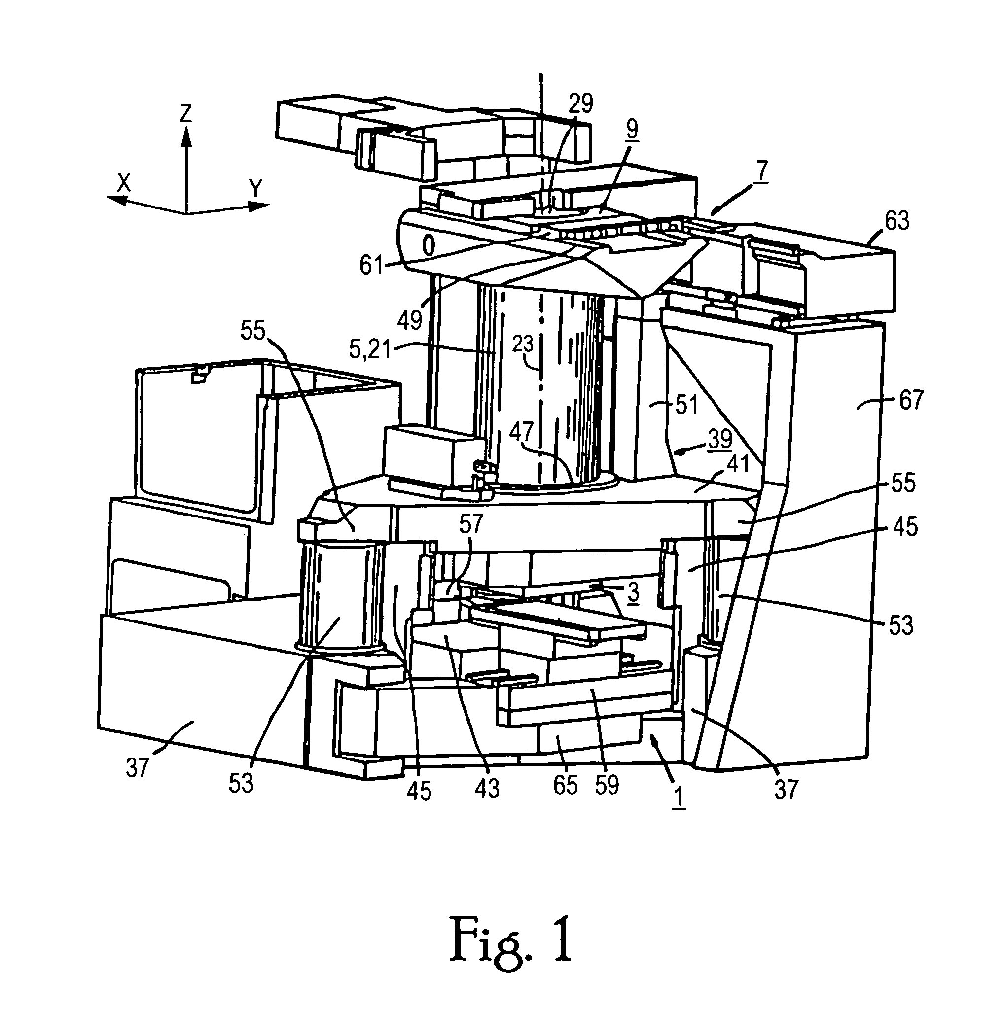
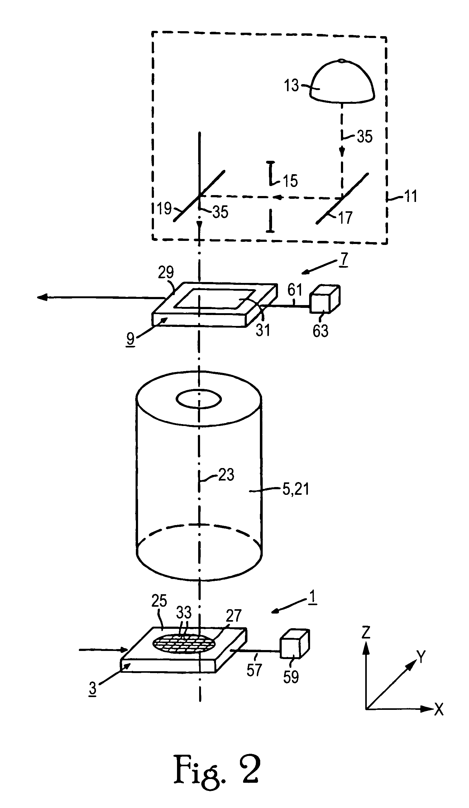
[0027]The example of a lithographic apparatus shown in FIGS. 1 and 2 is suitable for use in the manufacture of integrated semiconductor circuits by a lithographic process. As FIGS. 1, 2 show, the lithographic apparatus, seen from the ground along a vertical direction Z, is provided with, in that order, a positioning device 1 that includes a substrate holder 3 and a focusing unit 5, a further positioning device 7 that includes a mask holder 9, and a radiation source 11 (see FIG. 2).

[0028]The lithographic apparatus is an optical lithographic projection apparatus in which the radiation source 11 comprises a light source 13, a diaphragm 15, and mirrors 17 and 19. The focusing unit 5 is an imaging or projection system provided with an optical lens system 21, having an optical main axis 23 directed parallel to the Z-direction and an optical reduction factor which, for example, may be 4 or 5. However, the lithographic apparatus may likewise be of a different type comprising a different rad...


PUM

PropertyMeasurementUnit
frequencyaaaaaaaaaa
resonance frequencyaaaaaaaaaa
stiffnessaaaaaaaaaa

Abstract

A supporting device for supporting in a lithographic projection apparatus a supported part relative to a supporting part, is presented. The supporting device includes a first part that engages the supporting part of the lithographic projection apparatus; a second part that engages the supported part of the lithographic projection apparatus; a supporting spring system disposed between the first part and the second part; and a position control system configured to control a position of the supported part. The position control system comprises at least one reference object that is movable relative to the supporting part; a reference support device that supports the reference object relative to the first part, wherein the reference object and the reference support device form a reference mass-spring system; at least one position sensor that detects at least one attribute of the position of the second part relative to at least one of the reference objects, the position sensor including a sensor output for outputting a position signal representing at least one of the attributes; and an actuator, communicatively coupled to the position sensor, that is configured to adjust the position of the second part relative to the first part, in response to the position signal.

Description

BACKGROUND OF THE INVENTION[0001]1. Priority Information[0002]This application claims priority from European Patent Application No. 03077540.7, filed Aug. 11, 2003, and European Patent Application No. 03076923.6, filed Jun. 13, 2003, herein incorporated by reference in their entirety.[0003]2. Field of the Invention[0004]The present invention relates to a supporting device, a lithographic apparatus, a device manufacturing method, and a position control system.[0005]3. Description of the Related Art[0006]Lithographic projection apparatuses can be used, for example, in the manufacture of integrated circuits (ICs). In such a case, patterning device of the lithographic projection apparatus may generate a circuit pattern corresponding to an individual layer of the IC, and this pattern can be imaged onto a target portion (e.g. comprising one or more dies) on a substrate (silicon wafer) that has been coated with a layer of radiation-sensitive material (resist).[0007]In general, a single waf...

Claims


Application Information

Patent Timeline
Patent Type & Authority Patents(United States)
IPC IPC(8): G03B27/42G03B27/32G03B27/58F16F15/023G03B27/00F16F15/03F16F15/04G03F7/20H01L21/027
CPCF16F15/02G03F7/70933G03F7/709G03F7/70833
Inventor DAMS, JOHANNES ADRIANUS ANTONIUS THEODORUSAUER, FRANK
Owner ASML NETHERLANDS BV
Why Eureka
Try Eureka