Combined fuel injection and ignition means

a fuel injection and ignition means technology, applied in the direction of electric ignition installation, machines/engines, mechanical equipment, etc., can solve the problems of difficult construction of combined injection and ignition devices, difficult to ensure that the ignition current passes through this resistive element, etc., to prevent the impingement of fuel spray

Inactive Publication Date: 2006-08-08
ORBITAL ENGINE CO PTY LTD
View PDF9 Cites 106 Cited by
  • Summary
  • Abstract
  • Description
  • Claims
  • Application Information

AI Technical Summary

Benefits of technology

[0007]The primary electrode is typically an emitter electrode connected with an ignition coil or similar high voltage generating means. The primary electrode is typically isolated electrically from the remainder of the combined fuel injection and ignition means by insulating means. Accordingly the primary electrode is particularly suitable for locating the resistive element, as the insulating means can act to contain the ignition current so that the current is forced to flow through the resistive element; that is, the insulating means reduces the ability of the ignition current to follow a short circuit path around the resistive element. Where a resistive element is located in an electrical path to ground potential (ie on the ground side of the spark gap) it has been found by the applicant that it is difficult to ensure that the ignition current passes through this resistive element. Commonly, the current will attempt to track along the outside of any insulation that is provided around the outside of such a resistive element located on the ground side of the spark gap. Providing an insulated ground path of extended length has been found as a suitable solution to this problem, however this often makes the combined injection and ignition device difficult to construct. Accordingly, in a combined injection and ignition device, the injector can be seen as being particularly suited to forming a secondary electrode. In this regard the injector is preferably constructed so as to form a path to ground via any mechanical arrangement, such as a threaded collar, used for securing the combined ignition and injection device into the cylinder head or cylinder block of the engine. In this regard, the current may pass through a leg of the injector to the mechanical arrangement. Alternatively, the current may return to ground using the injector leg and passing through the solenoid used for actuating the injector.
[0019]The spark gap is preferably positioned within the path of such a fuel spray issuing from the valve head. In this way, a spark breaching the spark gap can directly ignite spray that has issued from the valve head. Preferably the spray issuing from the valve head penetrates the combustion chamber at a rate sufficient for the spark gap to still be in the path of the spray once the valve head has closed or commenced closing.
[0031]Although it is preferable to prevent impingement of fuel spray onto the nose of the insulator it is also preferable that at least part of inner axial portion of the primary electrode that extends beyond the nose of the insulator be located within the fuel spray so that the spray can cool the electrode.
[0037]According to a sixth aspect of the present invention there is provided a combined fuel injection and ignition means for a spark-ignition internal combustion engine; said combined fuel injection and ignition means comprising a fuel flow path with a delivery valve at a distal end thereof and an ignition path with a terminal member at a distal end thereof; said fuel flow path and said ignition path located in spaced apart relationship and at least a portion of said ignition path being electrically insulated from said fuel flow path; said combined fuel injection and ignition means adapted such that, in use, at least a portion of said ignition path projects internally of said combustion chamber a length sufficient to prevent shorting of electrical energy between said ignition path and a cylinder head of said engine.

Problems solved by technology

Where a resistive element is located in an electrical path to ground potential (ie on the ground side of the spark gap) it has been found by the applicant that it is difficult to ensure that the ignition current passes through this resistive element.
Providing an insulated ground path of extended length has been found as a suitable solution to this problem, however this often makes the combined injection and ignition device difficult to construct.

Method used


Image

  • Combined fuel injection and ignition means
  • Combined fuel injection and ignition means
  • Combined fuel injection and ignition means

Examples


Embodiment Construction

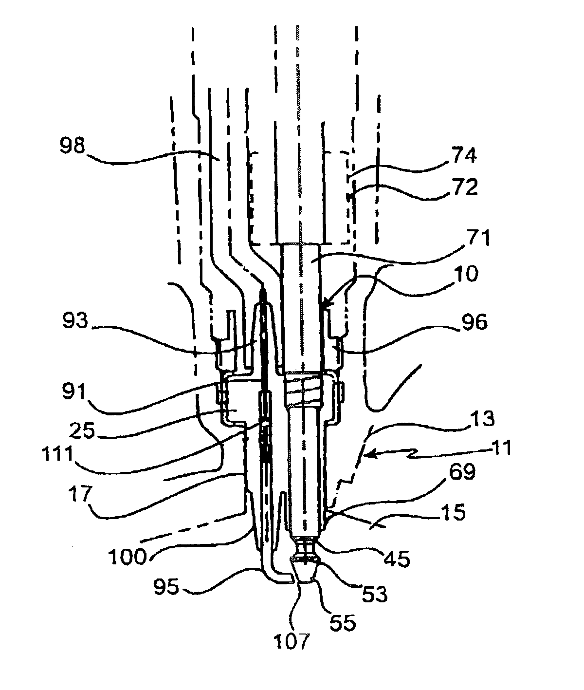
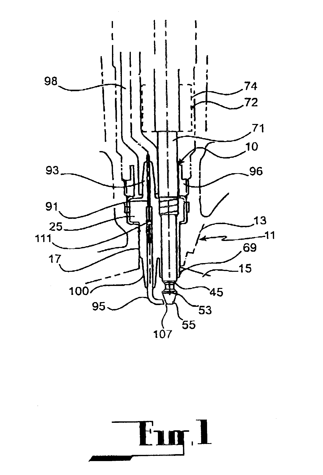
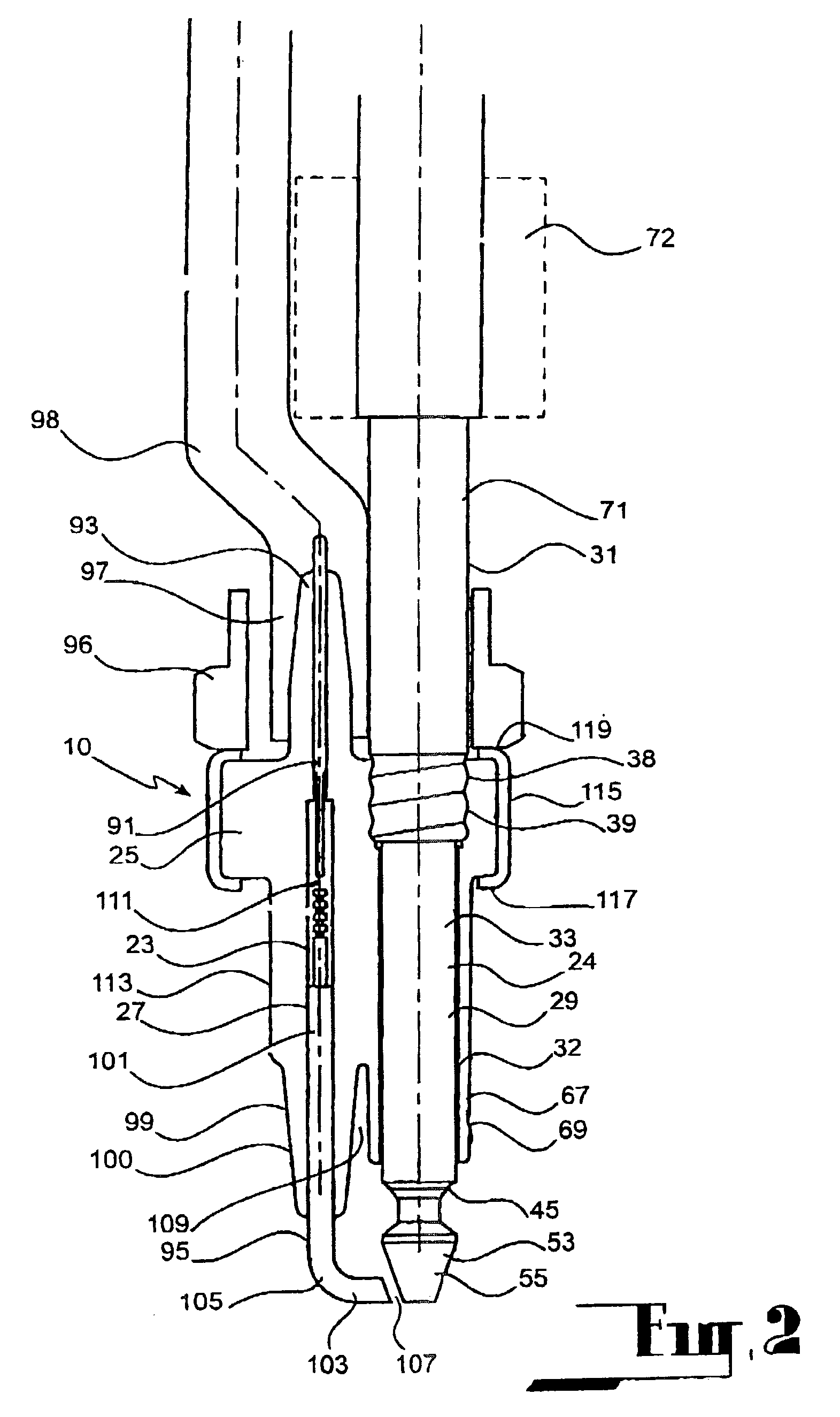
[0047]Referring to the drawings, a device 10 according to the embodiment provides a combined fuel injection and ignition means for a reciprocating piston internal combustion engine. The device 10 is equally applicable to two and four stroke engines.

[0048]The device 10 is also applicable to various forms of direct injection internal combustion engines, such as High Pressure Direct Injection engines, dual fluid injection engines (often referred to as gas assisted (or air assisted) direct injection engines) and other forms of direct injection engines.

[0049]The device 10 has particular application to combined fuel injection and ignition devices for spark ignited internal combustion engines that ignite fuel as it is delivered from a fuel delivery valve (or immediately after cessation of fuel delivery from a fuel delivery valve) of the device 10. Certain forms of such devices are referred to jet ignited or spray guided injectors.

[0050]In this embodiment, the device 10 will be described in...


PUM


Abstract

A device (10) providing a combined fuel injection and ignition means for a spark-ignition internal combustion engine. The device (10) comprises a insulator body (25) of ceramic material, a fuel flow path (24) having a section thereof encased in the insulator body (25) and terminating at a delivery port (45) disposed outwardly of the insulator body (25), and, an ignition path (23) having a section encased in the insulator body (25) in a spaced apart relationship with respect to the section of the fuel path (24). The fuel path (24) is defined within a valve structure (33) detachably secured to the insulator body (25) so as to be selectively removable therefrom. The ignition path (23) terminates at an electrode (95) disposed outwardly of the insulator body (25). The insulator body has a nose portion (100) and a skirt portion (69) beyond the delivery port (45). The nose (100) and the delivery port (45) are positioned relative to each other such that all or at least part of the fuel spray issuing from the delivery port (45) avoids impingement on the nose (100).

Description

TECHNICAL FIELD[0001]This invention relates to a combined fuel injection and ignition means for a spark-ignition internal combustion engine.BACKGROUND OF THE INVENTION[0002]Combined fuel and ignition means for spark-ignition internal combustion engines are known. Typical examples of arrangements involving combined fuel injection and ignition means are disclosed in U.S. Pat. No. 4,967,708 (Linder et al), EP 0 632 198 (Suzuki), U.S. Pat. No. 5,497,744 (Nagaosa et al), and U.S. Pat. No. 5,730,100 (Bergsten).[0003]In each of these arrangements, the fuel and high voltage ignition follow a common path through the device. Typically, fuel is delivered through a fuel delivery port defined between a valve seat and a valve needle. The valve needle is of electrically conductive material so as to provide the ignition path. This arrangement thus provides the common path for the fuel and the high voltage energy.[0004]In such devices the valve stem is believed to provide relatively high levels of c...

Claims


Application Information

Patent Timeline
Patent Type & Authority Patents(United States)
IPC IPC(8): F02M57/06F02M51/06F02P13/00F02M61/08F02M61/14F02M61/16F02M61/18F02M67/12F02P15/00
CPCF02M57/06F02M51/0671
Inventor MCKAY, MICHAEL LEONARD
Owner ORBITAL ENGINE CO PTY LTD
Why Eureka
Try Eureka