
Apparatus having improved wind resistance that is a synergistic combination of a windshield and a brooder heater pilot assembly

a pilot assembly and windshield technology, applied in the field of poultry brooder gas heaters, can solve the problems of false signal that the pilot light has been blown out, and achieve the effects of ensuring the safety of the brooder

Inactive Publication Date: 2006-08-08
GAS FIRED PRODS
View PDF11 Cites 8 Cited by
  • Summary
  • Abstract
  • Description
  • Claims
  • Application Information

AI Technical Summary

Benefits of technology

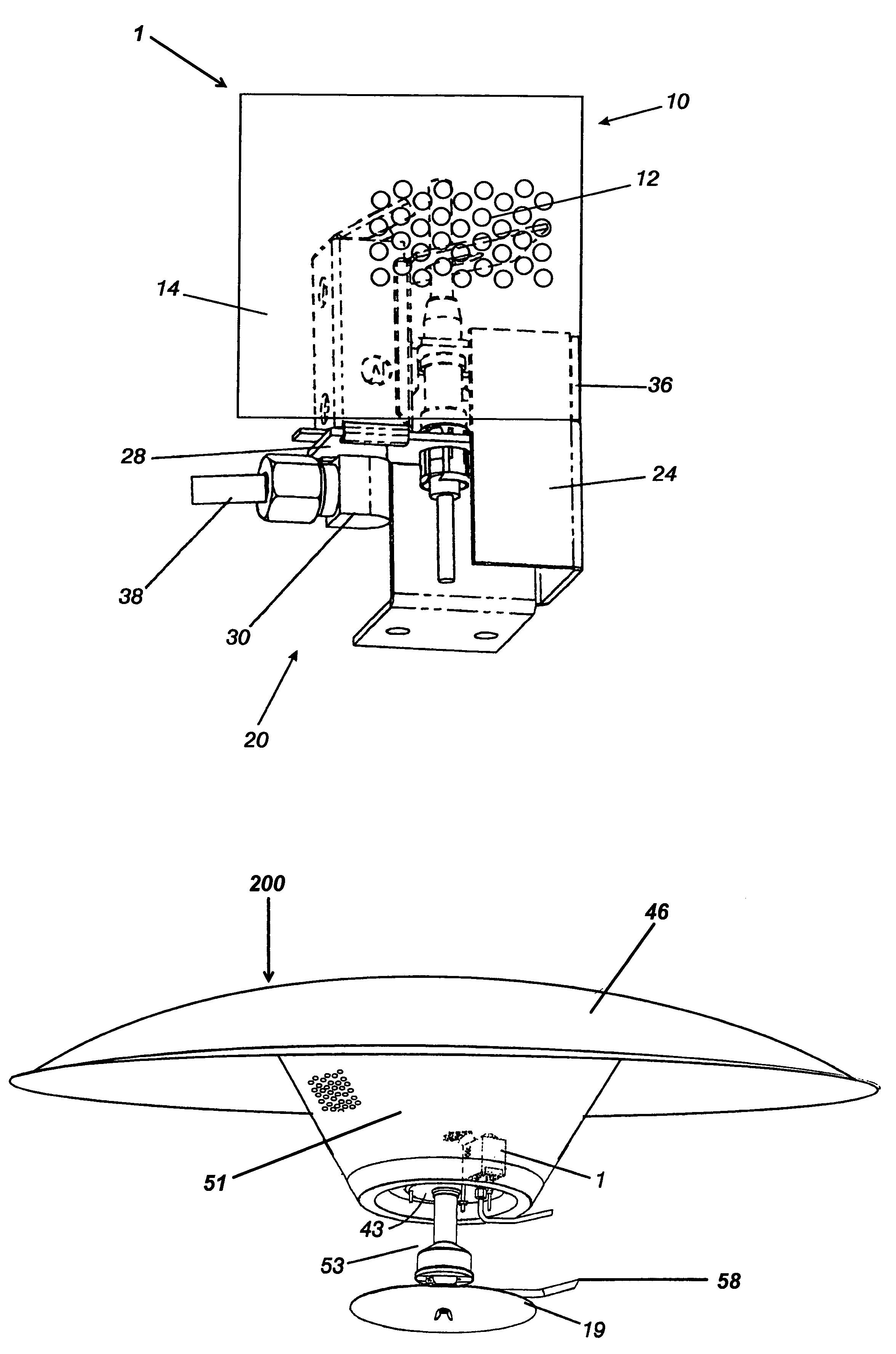
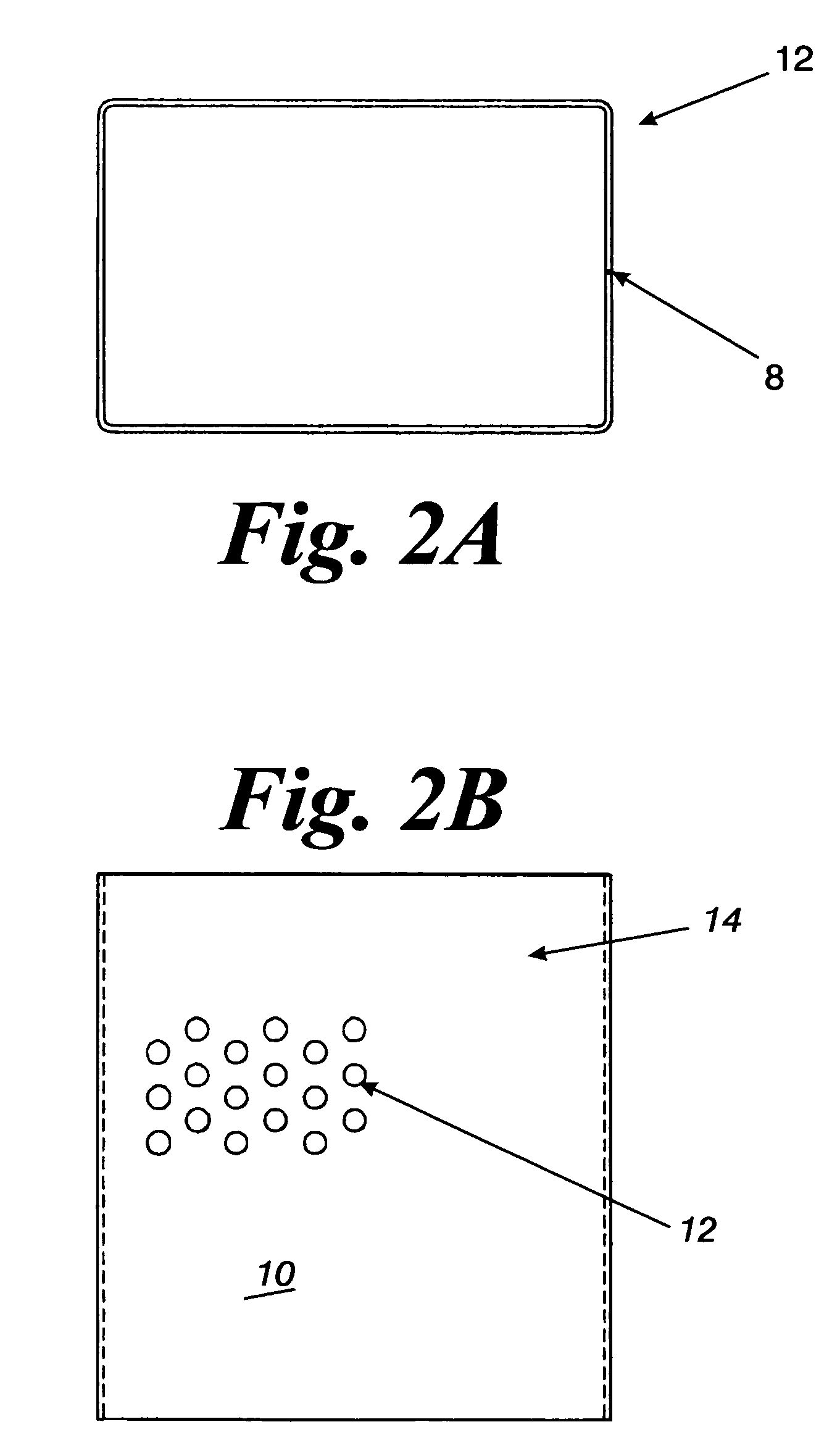
[0006]The invention is a windshield that works synergistically in concert with a gas pilot light assembly, which also has components that provide some protection from high air flow; wherein the windshield and pilot light assembly are an apparatus that ensures the dependable operation of a burner, and specifically the reliable operation of a brooder heater burner in high air flow conditions. The pilot assembly, which is mounted proximal to the burner, is comprised of a pilot light; a pilot light orifice; a vented pilot housing (stack) with a flame deflector cap; a pilot light gas line; a thermocouple with connecting electrical leads; a pilot base; a mounting bracket; and a pilot assembly windshield. The vented pilot housing can also have a thermocouple restrictor plate, which shields the thermocouple from updrafts and directs the flame toward the thermocouple. The restrictor plate ensures that the thermocouple is heated, and prevents an errant signal causing the gas supply line to close. The windshield, which is substantially a partially perforated chamber, has an open top and an open bottom, and at least one surrounding side wall that provides a shield against side winds, wherein the at least one surrounding side wall has a section that is partially perforated and a section that is solid, and the chamber is sufficient in size to entirely shields the gas pilot light assembly. The windshield is intersectingly slid onto the mounting bracket, provides a protected zone of air infusion for both the pilot flame and for the thermocouple. The mounting bracket is preferably slotted such that the windshield can be positioned by merely aligning the windshield with the slots on the mounting bracket, and sliding the windshield into the slots, or removed by merely sliding the windshield off the slots. The configuration enables the quick removal and replacement of the windshield. Likewise, the vented pilot housing can be simply lifted off the pilot base, enabling quick access to the pilot light orifice so that it can be easily cleaned. The easy removal of both the windshield and the vented housing reduces the servicing time, and in general results in a maintenance friendly brooder. Another feature of the apparatus is that the windshield need not be removed to ignite the pilot light. The pilot assembly can have either a vertical or a horizontal orientation or any angle in between. The pilot light flame is directed by the flame deflector cap and the restrictor plate so that it is very close or actually impinges the thermocouple.
[0007]Both ends of the windshield are open, enabling air to flow vertically with less shielding, while effectively deflecting crosswinds. The combination of the vented pilot housing with the flame deflector cap, restrictor plate, and the windshield produce a synergistic effect, enabling the poultry brooder heater to have superior tolerance to variations in air flow, and ease of cleaning. Furthermore, the apparatus enables the use of a pilot light having small jet orifice, which reduces gas consumption by the pilot light. The invented assembly enables the pilot light to reliably remain lit in air flows of 7–9 mph, and the thermocouple stays sufficiently warm that it does not generate a false signal that the pilot light is extinguished, therein causing the gas to the brooder to be shut off.
[0010]Accordingly, a first object of the present invention is to provide an apparatus for a brooder heater having a ceramic or radiant element, wherein the heater has enhanced operating reliability at higher air flows as compared to heaters fitted with conventional pilot light assemblies.
[0011]A second object of the present invention is to provide an improved pilot light assembly for a brooder heater having a ceramic or radiant element, wherein the thermocouple does not incorrectly sense that the pilot light is extinguished.
[0012]A third object of the present invention is to provide a windshield for an improved pilot light assembly for the brooder heater, wherein the pilot light is not extinguished at higher air flows as compared to conventional pilot light assemblies.
[0013]A fourth object of the present invention is to provide an apparatus for a brooder heater having a ceramic or radiant element, wherein the apparatus provides a maintenance friendly brooder having quick access to the pilot light orifice.

Problems solved by technology

A problem with the current heaters, and in particular poultry brooders having a radiant or ceramic heating element with a gas pilot light, is that when the air flow is above 3 mph there is sufficient flow to either blow the pilot light out or to displace the flame of the pilot light from the thermocouple, such that the thermocouple is cooled, thereby generating a false signal that the pilot light has been blown out.

Method used


Image

  • Apparatus having improved wind resistance that is a synergistic combination of a windshield and a brooder heater pilot assembly
  • Apparatus having improved wind resistance that is a synergistic combination of a windshield and a brooder heater pilot assembly
  • Apparatus having improved wind resistance that is a synergistic combination of a windshield and a brooder heater pilot assembly

Examples


Embodiment Construction

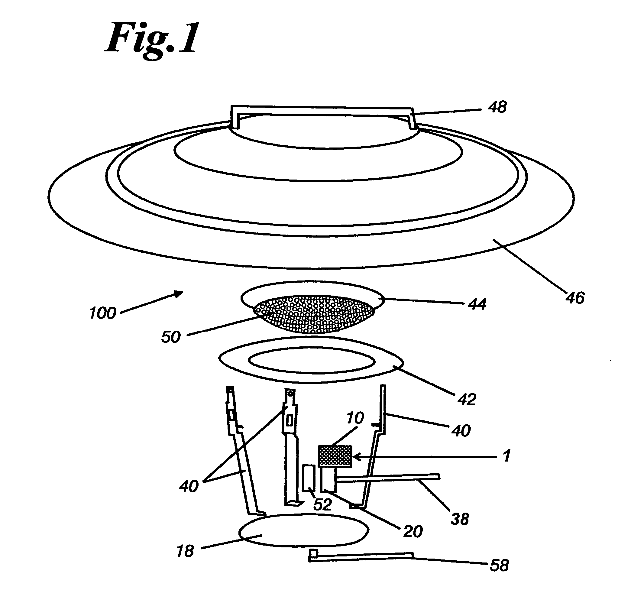
[0028]Referring now in particular to FIG. 1, there is illustrated a preferred embodiment of the poultry brooder in accordance with the present invention, indicated generally by reference numeral 100. As here embodied, poultry brooder heater 100 includes an inverted conical ceramic element 44 having radiant projections 50 protruding from and substantially covering the bottom surface of the element. The brooder heater 100, preferably, is suspended from overhead by attachment to the hanger 48, which is fitted to reflector 46. The ceramic element is seated on the ceramic holder ring 42. The ceramic holder ring 42 is held by support braces 40, at the point where the support braces have an outboard deflection. The upper end of the support braces 40 are removably mounted on the underside of reflector 46, thereby supporting the ceramic element 44, the holder ring 42, the pilot assembly 20, the burner 52 and the burner pan 18. The burner 52 and the pilot assembly 20 are mounted on the burner...


PUM


Abstract

The invention is an apparatus that is a synergistic combination of a windshield and a pilot light assembly for a gas burner heater. The apparatus provides reliable operation of the gas burner heater in high air flow conditions, where the air flow would normally cause the pilot light to be extinguished. The windshield, which is a partially perforated tubular chamber, provides a protected zone against high velocity air infusion for the entire pilot light assembly. The apparatus works in concert with the pilot light assembly, which also has components that provide protection from wind and can be quickly removed allowing quick cleaning and easy maintenance. The major components of the pilot light assembly are a pilot light orifice with a flame, a vented pilot housing (stack), a flame deflector cap, a pilot light gas line, a thermocouple with connecting electrical leads, a pilot base, a mounting bracket, and a windshield that surrounds the pilot light and the thermocouple. The flame deflector cap directs the flame toward the thermocouple. There is also a restrictor plate for restricting the flow of updrafts across the thermocouple and directing the flame toward the thermocouple. The invention is particularly useful in poultry brooder heaters, both ceramic and radiant, which are prone to failure as a consequence of the pilot light being blown out by the fresh air being drawn through the chicken house. The apparatus reduces the time to service a brooder.

Description

CROSS REFERENCE TO RELATED APPLICATION[0001]This application claims the benefit of U.S. Provisional Application No. 60 / 441,071 filed Jan. 18, 2003.FIELD OF THE INVENTION[0002]The present invention relates to a poultry brooder gas heater having a radiant or ceramic element, and more specifically, to an apparatus which is a synergistic combination of a windshield and an improved pilot light assembly having superior wind resistance.BACKGROUND OF THE INVENTION[0003]Maintaining proper brooding temperature is critical to effective poultry brooding since temperature variations cause chicks to expend energy to maintain body temperature rather than to increase body weight. Thus, it is desirable to keep the poultry house warm so that the food energy contained in the feed is used to produce weight gain by the bird rather than producing body heat. Furthermore, it is necessary to keep a continuous flow of air through the poultry house to dissipate ammonia that is generated as a waste product by ...

Claims


Application Information

Patent Timeline
IPC IPC(8): F23D14/12F23Q9/00A01K31/19
CPCA01K31/19
Inventor BRICE, MARTINMACINTOSH, FRANK W.
Owner GAS FIRED PRODS
Learn More